
Technical publication
Back to publications
Reactors & equipment
Cavitation-Assisted Particle Dispersion
okozyuk.com
Published
Read complete publication for whole-document Find and printing. Browser Find and native printing on this reader include only loaded content.
10 Scale-up, equipment selection, and troubleshooting
10.1 Parameters to preserve
No single similarity parameter guarantees scale up. A robust strategy preserves the variables that control the specific formulation:
-
Cavitation number or a validated geometry specific inception margin.
-
Local pressure drop profile and pressure recovery rate.
-
Critical passage dimension relative to the incoming coarse tail.
-
Local dissipation rate and collapse exposure.
-
Nominal passes and residence time distribution.
-
Solids loading, viscosity, surface tension, vapor pressure, and gas content.
-
Inlet and outlet temperature.
-
Stabilizer amount relative to newly created surface area.
-
Wear material and collapse location.
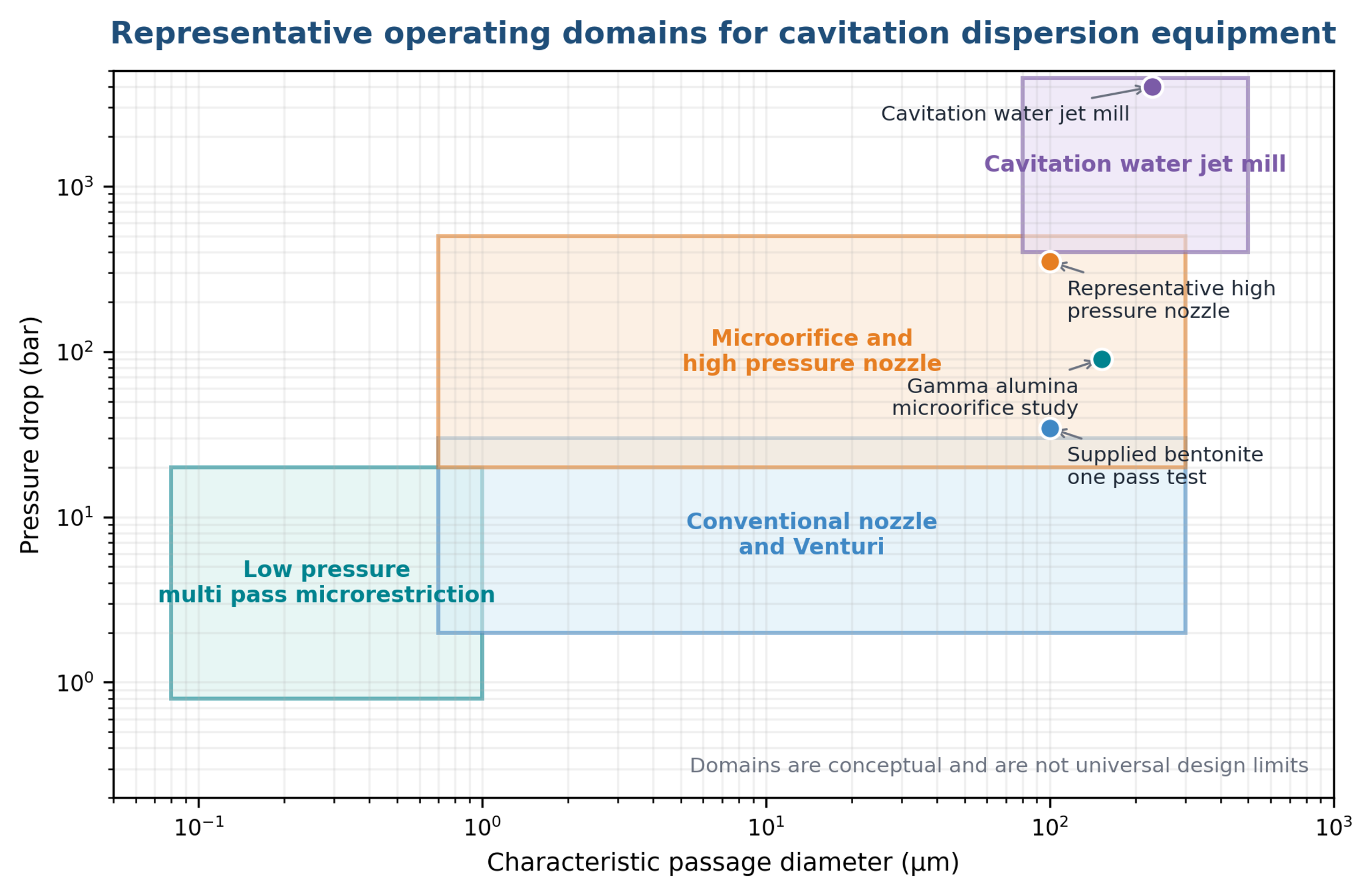
Figure 10.1. Representative operating domains for selected cavitation dispersion devices. Boundaries are conceptual, not universal design limits [58].
10.2 Throughput scaling by numbering up
For parallel geometrically identical passages, throughput can be increased by adding passages while preserving the pressure history in each element. This numbering up approach is often more reliable than enlarging one micro orifice because enlargement changes velocity gradients, cavity structure, and nuclei behavior. The manifold must distribute flow uniformly and avoid dead legs.
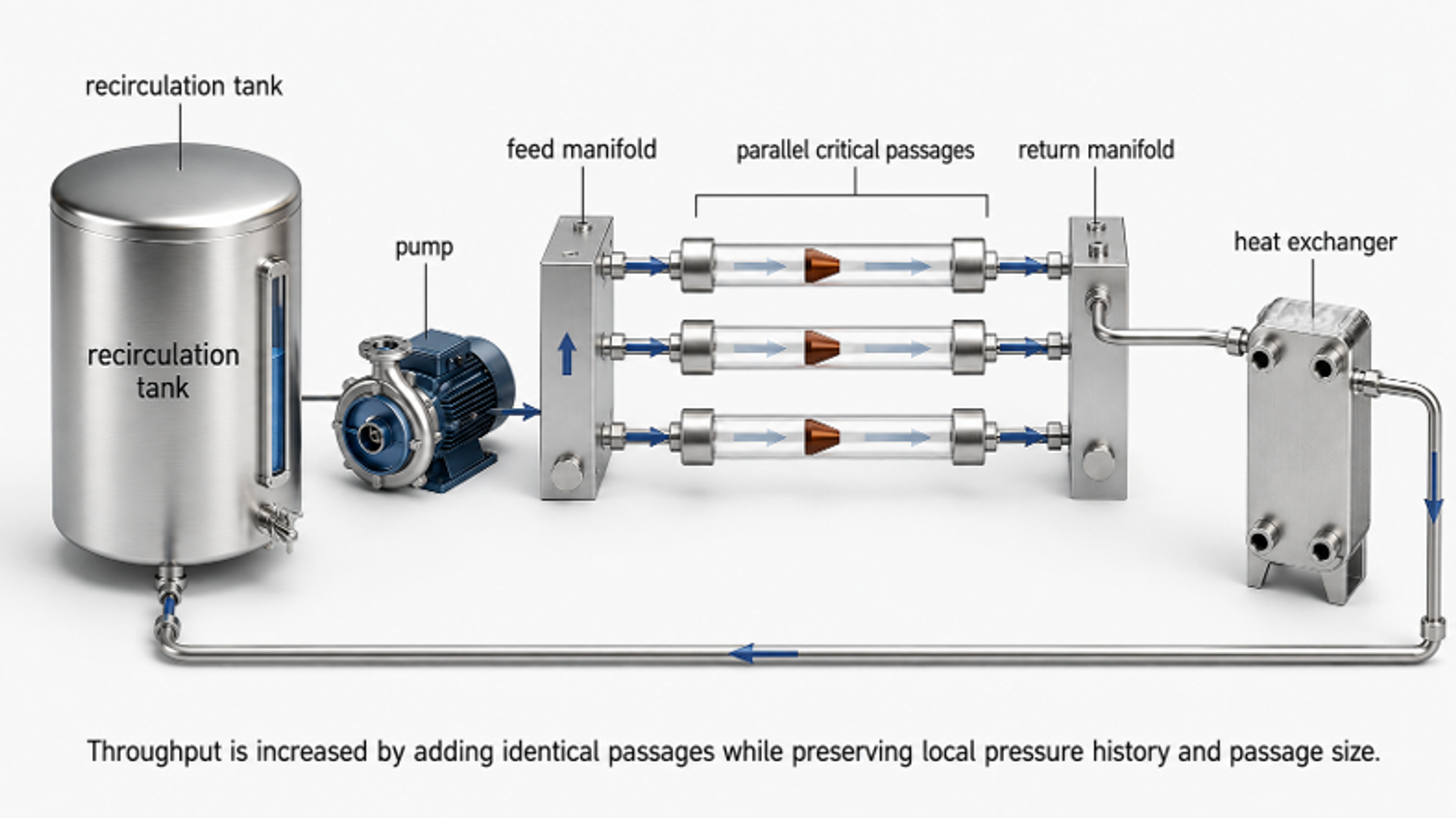
Figure 10.2. Numbering up of identical critical passages in a recirculating production loop [58].
For larger static reactors, scale up can increase the number of holes or stages while preserving hole diameter and pressure drop. For dynamic processors, tip speed, gap, stage count, and power per unit throughput are relevant, but equal tip speed does not guarantee equal cavity cloud structure. Pilot testing remains necessary.
10.3 Heat removal
Even when particle breakup is highly localized, most supplied power ultimately becomes heat. At steady state, the required heat exchanger duty is approximately:
where is motor power transferred to the process and the second term represents any allowable sensible temperature rise. The exchanger should be sized from measured power and temperature, not an assumed cavitation efficiency.
10.4 Stagewise development procedure
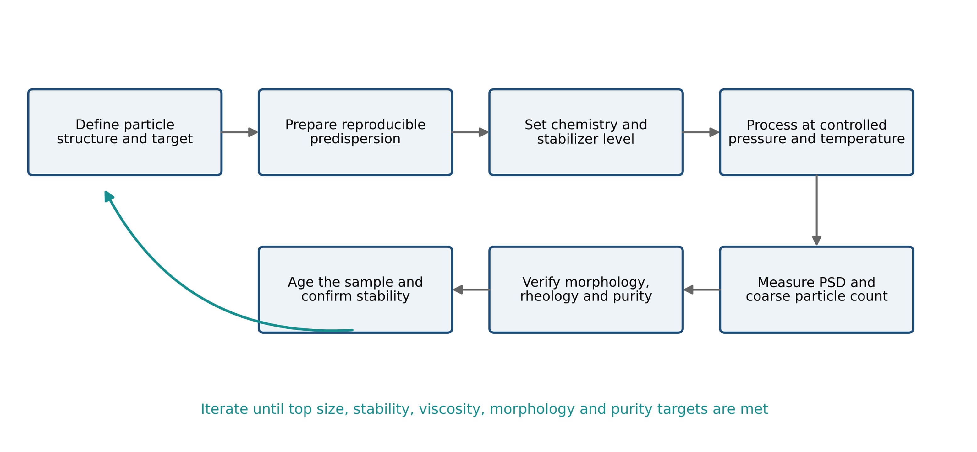
Figure 10.3. Recommended development workflow for cavitation-assisted particle dispersing.
A practical scale-up sequence is:
-
Establish a reproducible feed preparation and analytical method.
-
Define the primary particle, aggregate, agglomerate, and floc structure.
-
Determine the minimum pressure and pass count that meet immediate size targets.
-
Optimize stabilizer level and verify aged size and rheology.
-
Confirm morphology, crystal structure, and purity.
-
Measure temperature rise, pressure pulsation, flow, and wear.
-
Increase batch volume while preserving the same critical reactor.
-
Add parallel passages or stages before changing critical geometry.
-
Verify manifold balance and actual pass distribution.
-
Repeat aging, functional, cleaning, and contamination tests at production scale.
Table 10.1. Scale-up verification checks.
| Check | Laboratory evidence | Production verification |
|---|---|---|
| Cavitation inception | Pressure, flow, acoustic or visual response | Same operating margin at every parallel element |
| Exposure | Pass count and loop residence time | Tracer test or validated recirculation model |
| Product size | PSD and microscopy | At line PSD using retained reference method |
| Stabilization | Aged PSD, zeta potential, rheology | Storage, thermal cycling, and shipping simulation |
| Heat | Reactor inlet and outlet temperature | Heat exchanger duty and steady state balance |
| Wear | Short duration inspection and blanks | Campaign length elemental and dimensional checks |
| Cleanability | Bench cleaning test | Full skid drainability and validated cleaning cycle |
10.5 Troubleshooting
Table 10.2. Troubleshooting guide.
| Observation | Probable cause | Corrective action |
|---|---|---|
| Little size reduction | Cavitation not established, recovery too slow, agglomerates too strong, viscosity too high | Verify pressure and flow, modify geometry, increase passes, predilute, use staged processing |
| decreases but remains high | Bypass, poor tank mixing, plugging, small resistant population | Improve recirculation, inspect passages, add a coarse first stage, extend exposure cautiously |
| Size improves immediately but rebounds | Inadequate stabilizer, unfavorable pH or ionic strength, high collision rate | Add stabilizer before processing, adjust chemistry, reduce handling intensity after processing |
| Viscosity rises sharply | Increased surface area, network formation, excessive dispersion, temperature change | Optimize dispersant, reduce exposure, control temperature, verify solids concentration |
| Viscosity decreases but conductivity or strength worsens | Flake or fiber aspect ratio damage | Reduce pressure or passes, use larger passages, verify morphology |
| Metal concentration increases | Cavitation erosion or pump wear | Relocate collapse zone, change materials, install replaceable inserts, reduce severity |
| Coarse particles increase | Cavitation induced agglomeration or contamination | Review chemistry, gas content, pump suction, and stabilization; reduce cavitation |
| Poor repeatability | Variable nuclei, gas entrainment, temperature, sampling, or analytical dilution | Standardize degassing, tank level, temperature, sampling, and measurement protocol |
| Passage plugs | Incoming tail too large, sedimentation, poor premixing | Add screening or a coarse stage, increase passage size, improve tank suspension |
| Excessive foaming | Gas entrainment, surfactant, return line above liquid level | Submerge return, improve degassing, adjust formulation, reduce suction leakage |