
Technical publication
Back to publications
Reactors & equipment
Anti-Cavitation Control Valves
okozyuk.com
Published
Read complete publication for whole-document Find and printing. Browser Find and native printing on this reader include only loaded content.
Abstract
Cavitation in liquid control valves results from local pressure reduction below vapor pressure followed by vapor collapse during pressure recovery. The associated microjets, pressure waves, vibration, and unsteady hydraulic forces can cause trim erosion, pressure boundary damage, noise, loss of control authority, and reduced service life. This article presents a unified engineering treatment of cavitation physics, liquid valve sizing parameters, pressure recovery behavior, and anti-cavitation trim architecture. The discussion relates cavitation indices and liquid choking criteria to practical design strategies, including staged pressure reduction, opposed jet bubble isolation, stacked disk and concentric sleeve trims, axial multistage geometries, multipath trims, dirty service configurations, and fixed energy dissipators. Material selection, seat protection, outlet velocity, actuator stability, solids tolerance, and system layout are examined as coupled design variables. Application considerations are summarized for water distribution, power generation, oil and gas, petrochemical, and low flow injection services. A worked sizing example demonstrates preliminary severity assessment, choked flow capacity, stage count estimation, and hydraulic power dissipation. The article also reviews field diagnosis, maintenance, computational fluid dynamics, patent development, topology optimization, and additive manufacturing. Final valve selection should be based on the complete operating envelope and tested coefficients for the specific valve and trim geometry. Keywords: cavitation; control valves; anti-cavitation trim; pressure staging; liquid choking; valve sizing; severe service.
1. Introduction
Control valves regulate process variables by converting fluid pressure into irreversible hydraulic losses. In liquid service, the associated acceleration can reduce local static pressure below the liquid vapor pressure. Vapor cavities then form in high-velocity regions and collapse as pressure recovers. The resulting microjets, shock waves, unsteady forces, noise, and vibration can erode valve trim, damage the pressure boundary, loosen instrumentation, and reduce usable valve capacity. Cavitation is therefore both a fluid-dynamic phenomenon and a reliability concern. [1-3, 13-15, 21]
Anti-cavitation valve design follows two principal strategies. Cavitation elimination divides the total pressure loss among sufficient stages to keep local static pressure above the relevant vapor pressure throughout the trim. Cavitation control accepts limited vapor formation but directs bubble collapse toward the liquid core and away from metal surfaces. Selection between these strategies depends on pressure ratio, absolute pressure, flow range, fluid vapor pressure, fluid cleanliness, particle size, shutoff requirements, allowable noise, valve size, and exposure duration. [1, 2, 4, 5, 11, 14, 15]
No single trim geometry is optimal for every service condition. Small drilled passages provide high hydraulic resistance in a compact volume but are susceptible to plugging. Larger tortuous passages tolerate debris but require greater trim volume. Radial disk stacks distribute flow circumferentially, whereas axial trims can keep all pressure-reduction stages active throughout the stroke. Opposed jets can protect surfaces under mild cavitation, while severe pressure ratios generally require multistage designs. Valve selection should therefore match the hydraulic mechanism to the complete process envelope rather than infer suitability from line size alone. [2, 5, 9-12, 14, 15]
1.1 Scope of the Article
This article addresses liquid control valves and related fixed energy dissipators used for pressure reduction, flow control, pump recirculation, spray water, injection, distribution systems, reservoir filling, continuous relief, and high-pressure liquid letdown. Gas-noise trim is discussed only where the same geometric mechanisms are also applicable to liquid service. Flashing is treated separately from cavitation because vapor persists downstream and therefore requires a different mitigation strategy. [1, 2, 13-15]
The engineering relations are presented for preliminary calculation and conceptual design. Final sizing should use the applicable edition of IEC 60534 or the corresponding ISA adoption together with tested valve coefficients for the exact body, trim, flow direction, travel, and attached fittings. Relevant standards include IEC 60534-2-1 for installed flow-capacity equations, IEC 60534-2-3 for capacity test procedures, IEC 60534-8-2 for laboratory measurement of hydrodynamic noise, IEC 60534-8-4 for hydrodynamic noise prediction, and ISA-RP75.23-1995 (R2024) for evaluation of control-valve cavitation. [16-20]
1.2 Cavitation, flashing, and liquid choking
Cavitation occurs when local liquid pressure falls sufficiently to produce vapor and subsequently rises above vapor pressure, causing the vapor structures to condense. Flashing begins by the same mechanism, but the downstream pressure does not recover above vapor pressure, so vapor persists as a two-phase stream. Liquid choking occurs when vapor formation limits mass flow. After the critical condition is reached, further reduction of downstream pressure produces little or no increase in flow for a fixed upstream state and valve opening. [1-3, 13-15]
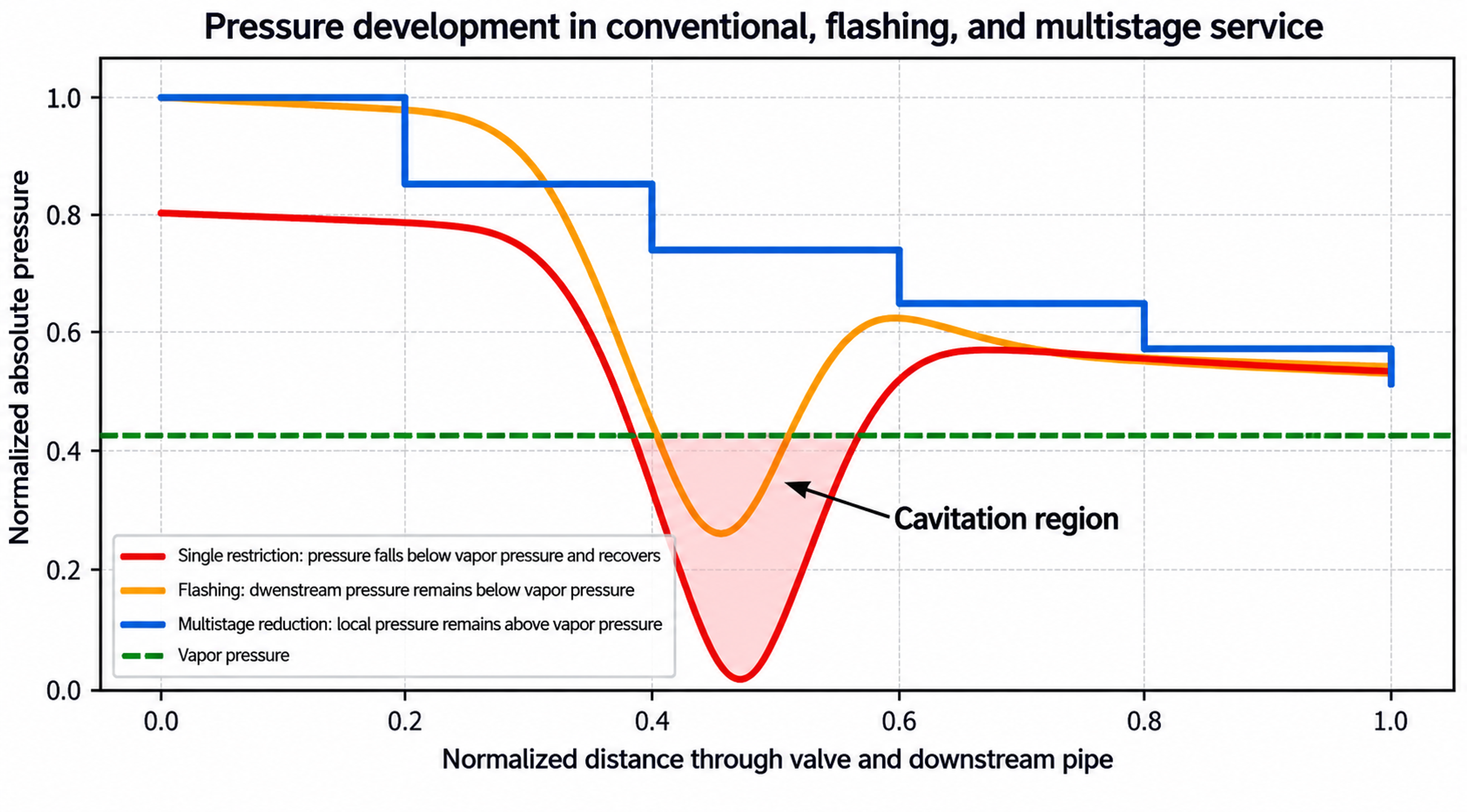
Figure 1. Comparison of conventional cavitating flow, flashing, and staged pressure reduction.
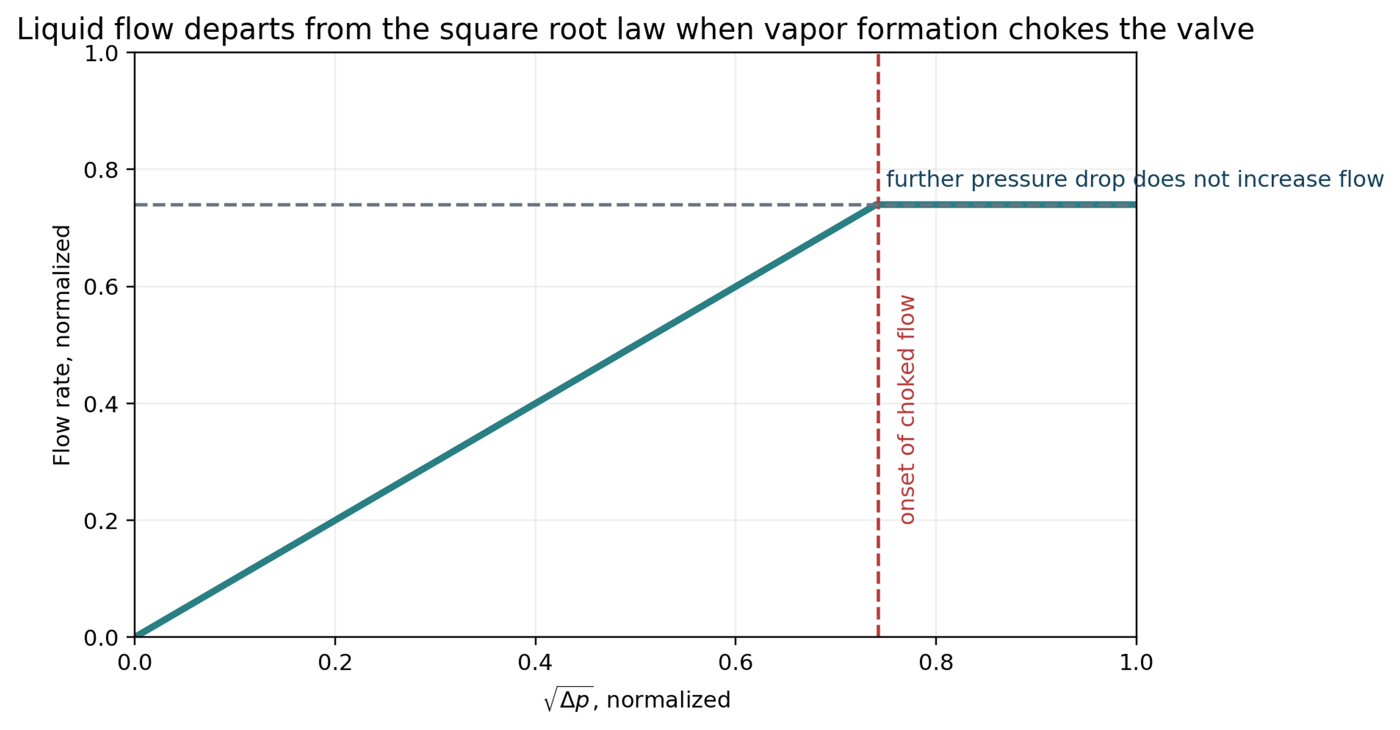
Figure 2. Idealized transition from the square root flow relation to liquid choked flow.
1.3 Consequences for the process plant
At incipient cavitation, the audible signature may begin as crackling and progress to hissing, rattling, or a gravel-like sound as the cavity field develops. These observations are useful diagnostic indicators, but airborne noise is not a direct measure of material damage. Harmful collapse can occur without exceptionally high external noise, and vibration can propagate into the actuator, positioner, tubing, pipe supports, and connected equipment. [1, 2, 10, 11, 14, 15]
Cavitation damage generally occurs downstream of the controlling restriction. Typical surfaces exhibit irregular pitting, edge loss, seat-line erosion, and, in severe cases, penetration of the pressure boundary. Repeated impact by microjets and pressure waves can remove passive oxide films and accelerate subsequent corrosion. Seat leakage is particularly damaging because a leakage jet may cavitate continuously while the valve is nominally closed. [2, 3, 13-15, 21]
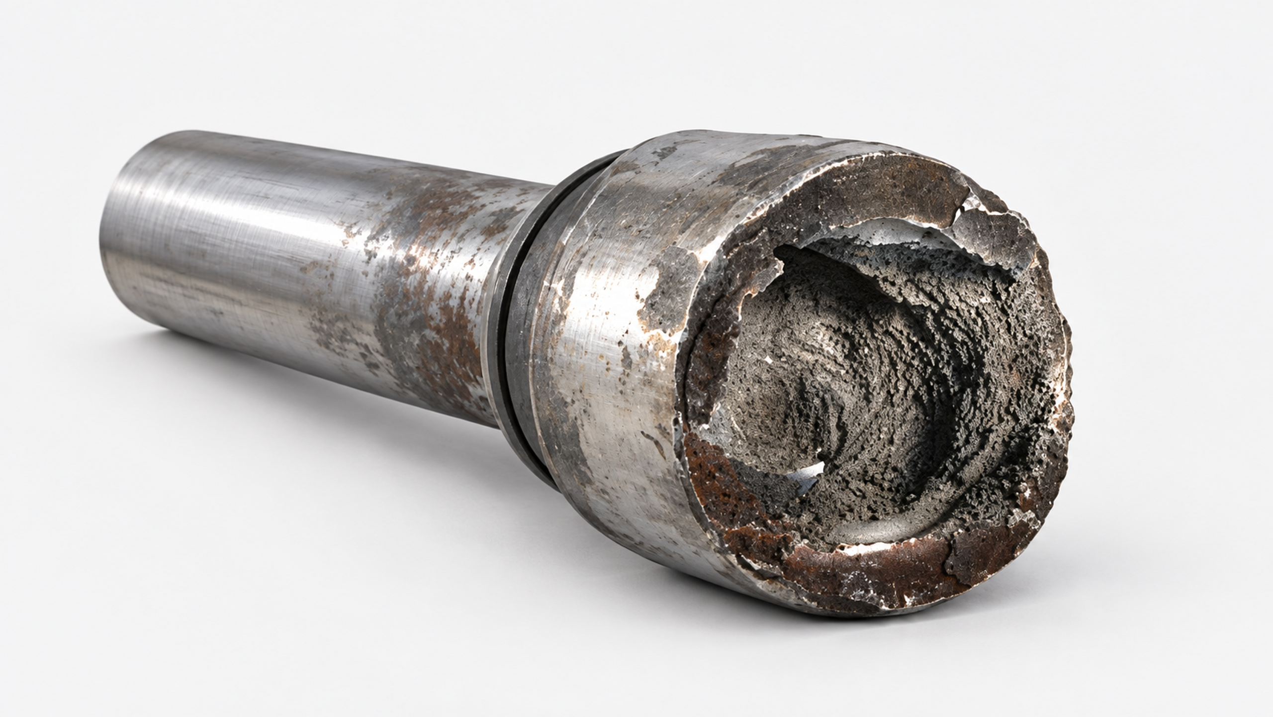
Figure 3. Cavitation damage and factors that control material loss.