
Technical publication
Back to publications
Reactors & equipment
Anti-Cavitation Control Valves
okozyuk.com
Published
Read complete publication for whole-document Find and printing. Browser Find and native printing on this reader include only loaded content.
Abstract
Cavitation in liquid control valves results from local pressure reduction below vapor pressure followed by vapor collapse during pressure recovery. The associated microjets, pressure waves, vibration, and unsteady hydraulic forces can cause trim erosion, pressure boundary damage, noise, loss of control authority, and reduced service life. This article presents a unified engineering treatment of cavitation physics, liquid valve sizing parameters, pressure recovery behavior, and anti-cavitation trim architecture. The discussion relates cavitation indices and liquid choking criteria to practical design strategies, including staged pressure reduction, opposed jet bubble isolation, stacked disk and concentric sleeve trims, axial multistage geometries, multipath trims, dirty service configurations, and fixed energy dissipators. Material selection, seat protection, outlet velocity, actuator stability, solids tolerance, and system layout are examined as coupled design variables. Application considerations are summarized for water distribution, power generation, oil and gas, petrochemical, and low flow injection services. A worked sizing example demonstrates preliminary severity assessment, choked flow capacity, stage count estimation, and hydraulic power dissipation. The article also reviews field diagnosis, maintenance, computational fluid dynamics, patent development, topology optimization, and additive manufacturing. Final valve selection should be based on the complete operating envelope and tested coefficients for the specific valve and trim geometry. Keywords: cavitation; control valves; anti-cavitation trim; pressure staging; liquid choking; valve sizing; severe service.
10. Patents, Computational Design, and Emerging Directions
10.1 Selected Patent Development
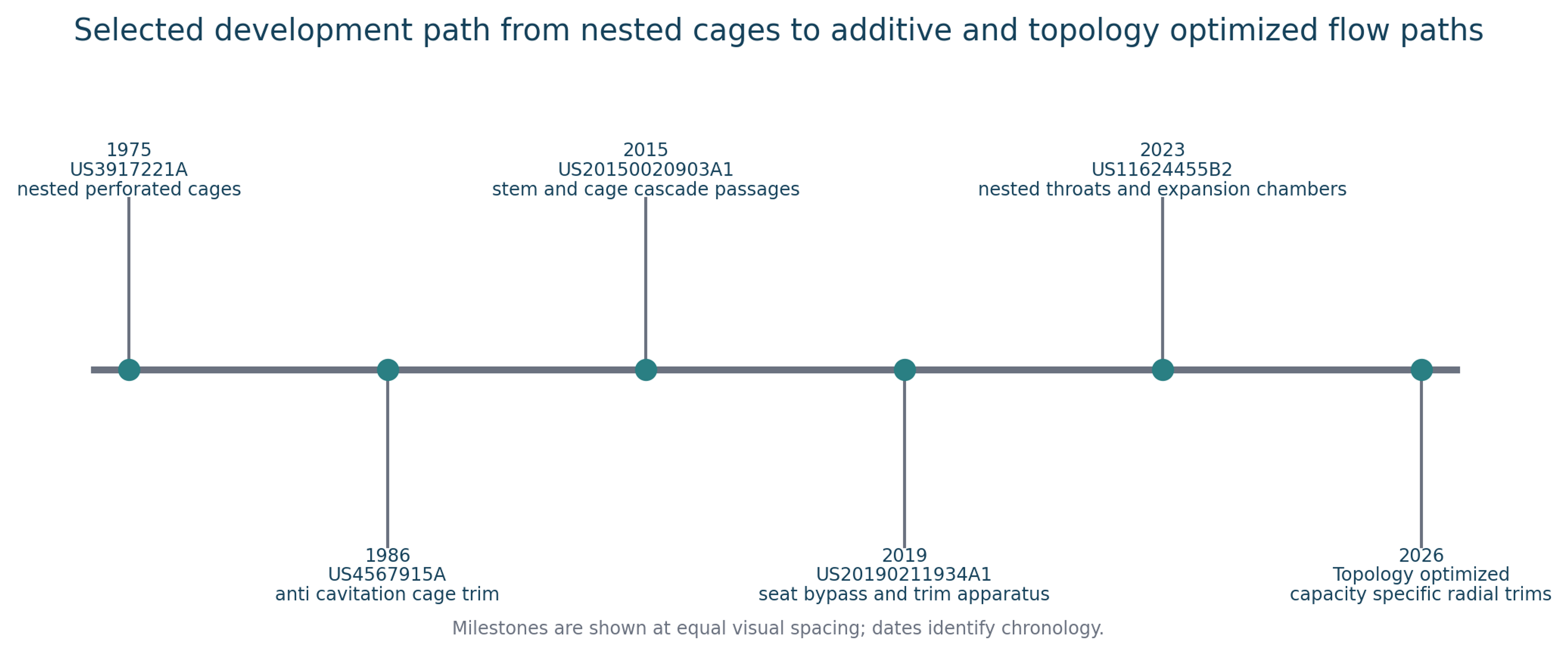
Figure 37. Selected anti-cavitation trim development from nested cages to optimized flow networks.
US3917221A describes a high-pressure-drop valve with multiple nested perforated cages that divide pressure reduction among several stages. US4567915A develops an anti-cavitation, low-noise cage trim for high pressure reduction. US20150020903A1 forms cascade passages jointly in a moving stem and surrounding cage so that different multistage columns open and close with stroke. US20190211934A1 addresses cage and seat arrangements that can maintain a flow path for minimum-flow or noise-reduction functions. US11624455B2 uses parallel passages containing throats and expansion chambers in a compact nested arrangement. [26-30]
Recurring inventive themes include multiplication of pressure-reduction stages, compact passage packing, increased wetted perimeter, controlled expansion, protected seats, debris management, and maintenance of the required flow characteristic over valve travel. These themes are consistent with the manufacturer architectures discussed above. Patent literature also illustrates how additive manufacturing can enable internal passages that are difficult to produce by conventional machining. [25-30]
10.2 CFD and Cavitation Models
Research on sleeve and multistage control valves commonly uses Reynolds-averaged or scale-resolving turbulence models coupled with homogeneous-mixture cavitation models. Qiu and coauthors analyzed pressure drop and cavitation in a sleeve regulating valve. Li and coauthors compared cavitation-modeling approaches and showed how cage design can confine the cavity region. Sun and coauthors investigated flow characteristics in a high-parameter multistage sleeve valve. These studies show that predictions are sensitive to turbulence treatment, nucleation parameters, mesh resolution, pressure boundary conditions, and the selected mass-transfer model. [22-24]
CFD is particularly useful for comparing geometries, locating low-pressure cores, estimating the distribution of pressure drop among stages, and determining whether high-velocity jets impinge on solid surfaces. Predictions should be validated against capacity, pressure, noise, visualization, or erosion data. A smooth mean-pressure field does not by itself demonstrate the absence of instantaneous local cavitation. [15, 22-24]
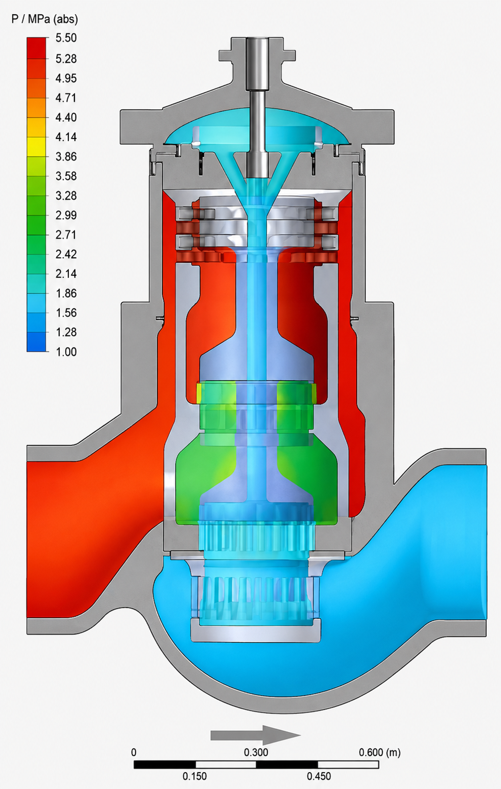
Figure 38. Pressure distribution through Fisher Dirty Service Trim in a NPS 16 easy-e™ valve body.
10.3 Topology Optimization and Additive Manufacturing
Butler, Alexandersen, and Rao presented a density-based topology-optimization framework for capacity-specific radial anti-cavitation trims. Material distribution within a design domain is treated as an optimization variable to obtain a manufacturable flow network with the target capacity while distributing hydraulic losses. This approach can reduce dependence on repeated standard hole patterns and enable passages tailored to a specific operating envelope. [25]
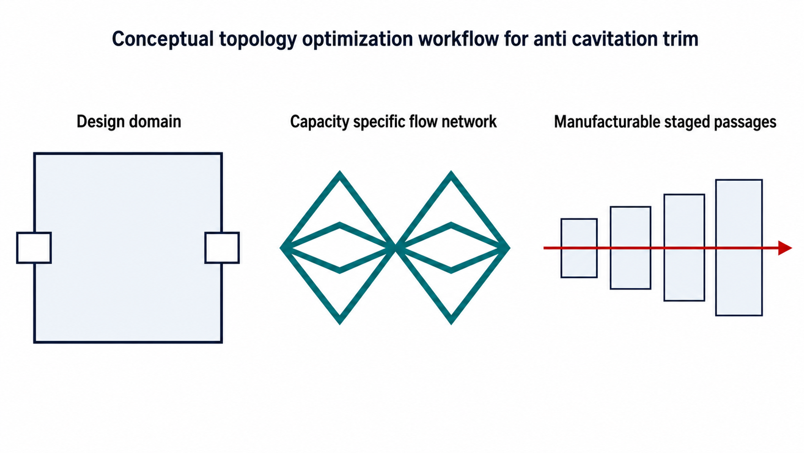
Figure 39. Conceptual workflow from design domain to an optimized staged flow network.
Additive manufacturing expands geometric freedom but introduces additional qualification requirements, including surface roughness, internal powder removal, minimum-passage inspection, dimensional tolerance, anisotropy, residual stress, heat treatment, repairability, and repeatable flow testing. A hydraulically advantageous flow path is useful only if it can be manufactured, cleaned, inspected, and reproduced reliably. [25, 28, 30]