
Technical publication
Back to publications
Reactors & equipment
Anti-Cavitation Control Valves
okozyuk.com
Published
Read complete publication for whole-document Find and printing. Browser Find and native printing on this reader include only loaded content.
Abstract
Cavitation in liquid control valves results from local pressure reduction below vapor pressure followed by vapor collapse during pressure recovery. The associated microjets, pressure waves, vibration, and unsteady hydraulic forces can cause trim erosion, pressure boundary damage, noise, loss of control authority, and reduced service life. This article presents a unified engineering treatment of cavitation physics, liquid valve sizing parameters, pressure recovery behavior, and anti-cavitation trim architecture. The discussion relates cavitation indices and liquid choking criteria to practical design strategies, including staged pressure reduction, opposed jet bubble isolation, stacked disk and concentric sleeve trims, axial multistage geometries, multipath trims, dirty service configurations, and fixed energy dissipators. Material selection, seat protection, outlet velocity, actuator stability, solids tolerance, and system layout are examined as coupled design variables. Application considerations are summarized for water distribution, power generation, oil and gas, petrochemical, and low flow injection services. A worked sizing example demonstrates preliminary severity assessment, choked flow capacity, stage count estimation, and hydraulic power dissipation. The article also reviews field diagnosis, maintenance, computational fluid dynamics, patent development, topology optimization, and additive manufacturing. Final valve selection should be based on the complete operating envelope and tested coefficients for the specific valve and trim geometry. Keywords: cavitation; control valves; anti-cavitation trim; pressure staging; liquid choking; valve sizing; severe service.
9. Diagnostics, Monitoring, and Maintenance
9.1 Diagnostic Sequence
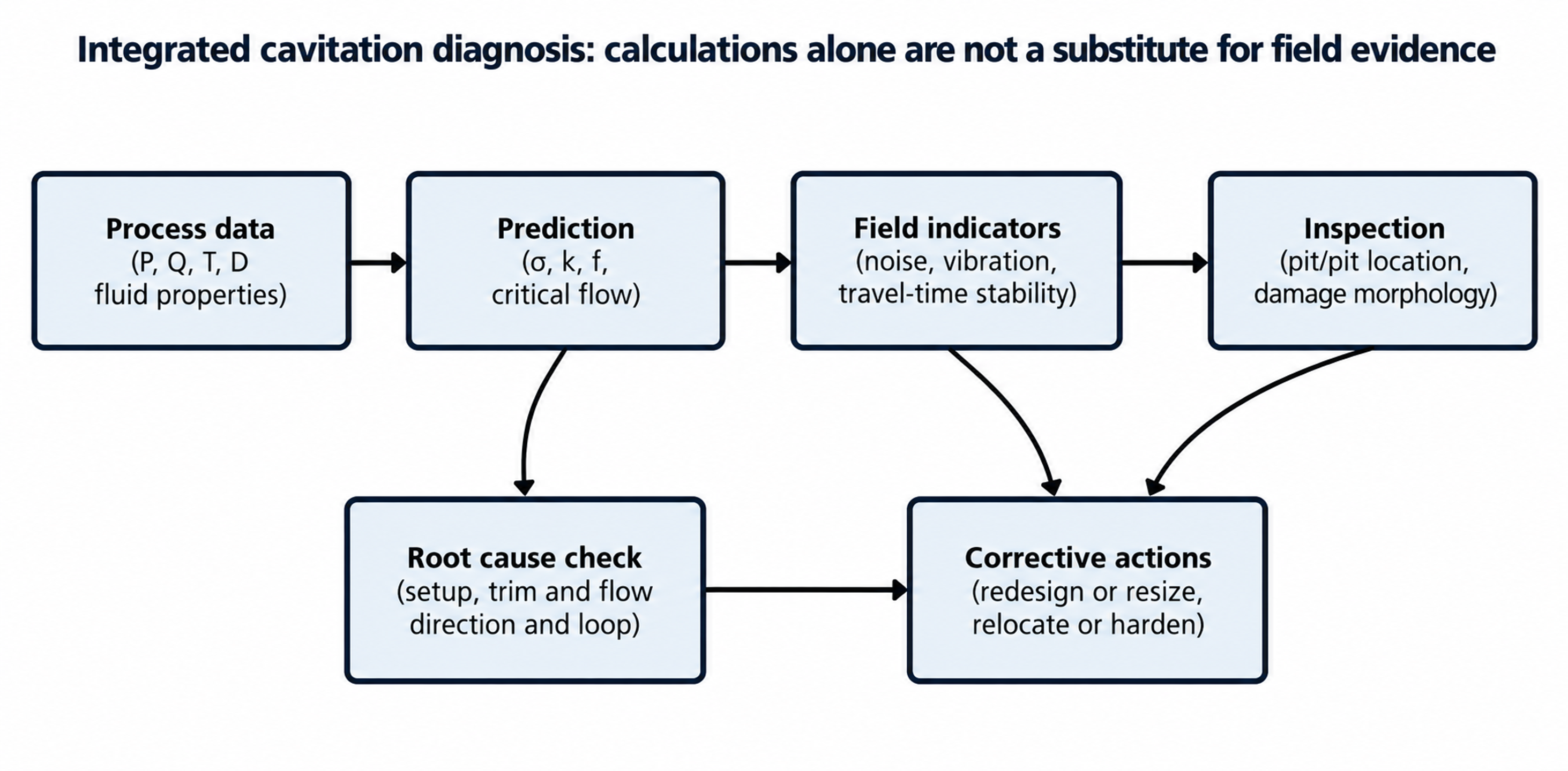
Figure 36. Integrated diagnostic sequence for a suspected cavitation problem.
Diagnosis should begin by reconstructing the actual operating point from calibrated upstream and downstream absolute pressures, fluid temperature, flow rate, and valve position. The operating pressure ratio should then be compared with the tested coefficient at the corresponding travel. Trends in noise, vibration, actuator motion, and process stability should be examined, followed by inspection of the trim and downstream pipe to determine the location and morphology of damage. [2, 3, 14, 15]
9.2 Useful Measurements
| Measurement | Value | Limitation |
|---|---|---|
| Upstream and downstream pressure | Confirms actual pressure ratio and transients | Slow transmitters can miss short surges. |
| Temperature | Establishes vapor pressure | A remote temperature may not represent the valve inlet. |
| Valve travel and command | Identifies low travel severe cases and instability | Position feedback may not show plug vibration. |
| Accelerometers | Detect structural response and changes over time | Resonance can amplify or mask the source. |
| Acoustic emission or high frequency pressure | Sensitive to incipient collapse events | Requires a baseline and careful sensor mounting. |
| Airborne sound | Useful for exposure and gross severity | Damage can occur without extreme airborne sound. |
| Inspection and replicas | Confirms damage location and morphology | Requires outage or removable trim access. |
Table 3. Measurements for cavitation diagnosis.
9.3 Damage Interpretation
Pitting downstream of the seat, especially on the body floor or plug flank, is consistent with a pressure-recovery region that reaches a solid boundary. Symmetric damage around a perforated cage suggests an intense but circumferentially distributed cavity field. One-sided erosion can indicate inlet asymmetry, misalignment, guide damage, an elbow located too close to the valve, or partial blockage. Wire drawing across the seat indicates leakage or throttling at the shutoff edge. [1-3, 10, 12, 15]
Corrosion pitting tends to occur in stagnant or crevice regions, whereas cavitation erosion is associated with high velocity and pressure recovery. Where damage mechanisms overlap, interpretation should include metallography, deposits, fluid chemistry, and operating history. Replacing damaged trim with the same material without correcting the hydraulic pressure profile commonly reproduces the failure. [2, 3, 15]
9.4 Maintenance Strategy
Maintenance should include inspection of all stage passages, dimensional verification of plug and cage clearances, stem straightness, guide wear, seat contact, balance seals, hardfacing condition, and evidence of fretting. Fine-passage trims require flushing and cleanliness control during commissioning. Spare trim should be stored with verified stage and hole patterns because visually similar cages can have different flow coefficients. [1, 2, 5, 9-12, 15]
Trend-based maintenance is preferable to waiting for leakage or gross failure. A rising vibration signature, increasing actuator activity, or a change in acoustic spectrum at the same process point can indicate erosion, blockage, or loss of guidance. Digital valve diagnostics can identify friction and positioning changes, but these data should be interpreted together with process pressure and flow measurements. [10, 15]