
Technical publication
Back to publications
Industrial applications
Vegetable Oil Refining, Biodiesel, and Oleochemical Conversion
okozyuk.com
Published
Updated
Read complete publication for whole-document Find and printing. Browser Find and native printing on this reader include only loaded content.
3 Engineering Fundamentals and Reactor Configurations
3.1 Flow, pressure, and cavitation onset
For incompressible flow, volumetric flow rate is related to flow area and mean velocity by the continuity equation:
When the flow area decreases, velocity increases. A pressure form of the mechanical energy balance between two locations is:
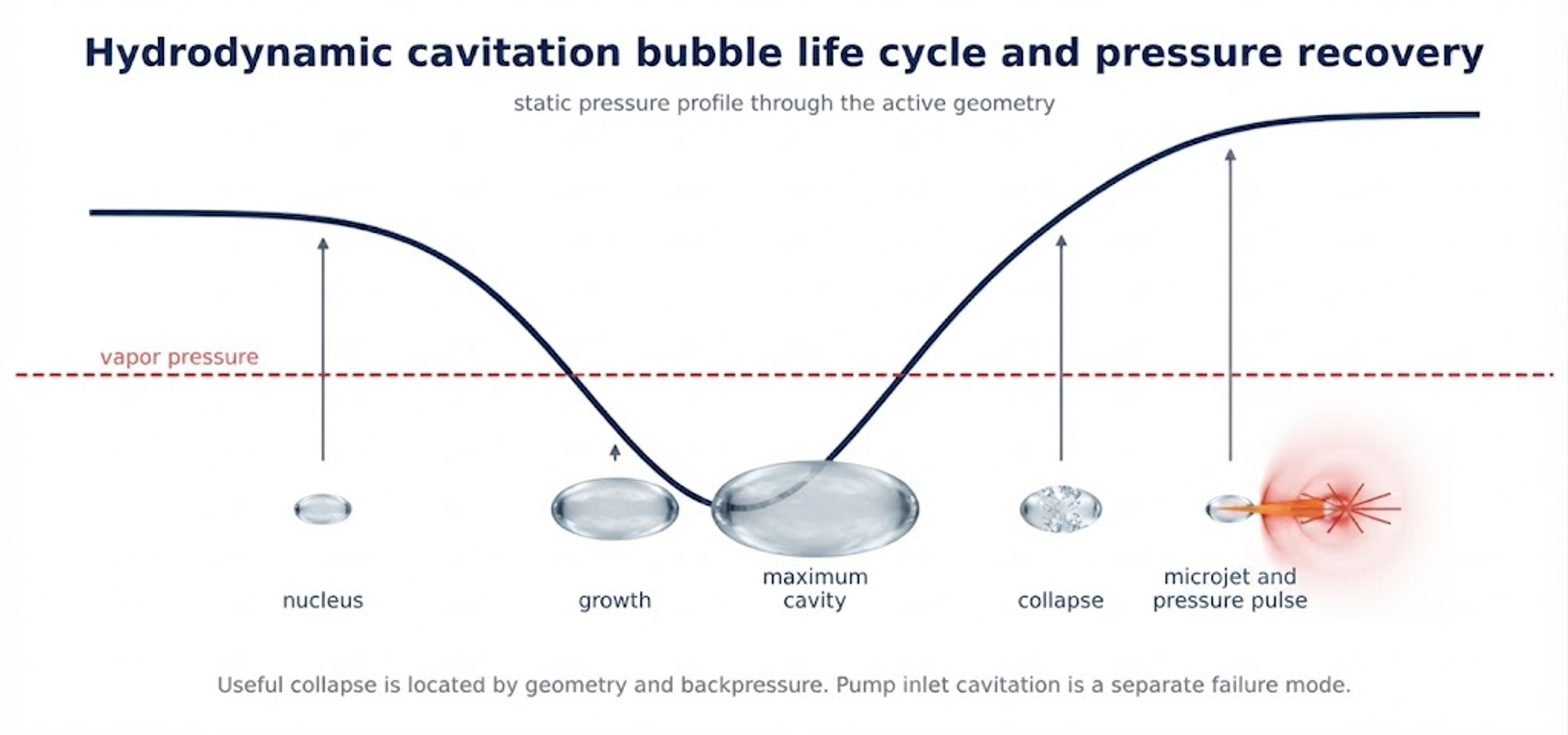
The static pressure can fall near or below the local vapor pressure in a throat, annular gap, rotating cavity, vortex core, or jet. The cavitation number is commonly written as:
Lower values generally indicate a greater tendency to cavitate, but comparisons are valid only when reference pressure, velocity location, temperature, and vapor pressure are defined consistently. In oil systems, dissolved gas and volatile alcohol can make the cavity content different from pure oil vapor. The Reynolds number provides a first indication of flow regime:
Reynolds number alone does not define cavitation intensity, because pressure recovery, nuclei, turbulence scale, and geometry determine where cavities grow and collapse. The Rayleigh Plesset equation expresses the radial dynamics of an ideal spherical bubble:
The equation demonstrates why pressure history, viscosity, surface tension, and gas content matter. Industrial cavities are not isolated spheres and often occur near walls, interfaces, particles, and rapidly changing turbulent structures. The equation is therefore a physical guide, not a complete reactor model [5-9].
3.2 Hydraulic power, energy dose, and heat
The hydraulic power dissipated across the active device is defined by Equation 3.6:
The approximate electrical input required for the pressure-generating pump is calculated using Equation 3.7:
For a single pass, the idealized specific electrical energy is given by Equation 3.8:
Hydraulic energy ultimately becomes sensible heat, kinetic energy, pressure recovery loss, acoustic emission, vibration, surface work, and deformation of dispersed phases. If all pressure loss becomes sensible heat in an adiabatic pass, the upper estimate of bulk temperature rise is calculated via Equation 3.9:
A modest single pass temperature rise can become large during recirculation. Temperature is not a secondary utility variable. It changes viscosity, vapor pressure, enzyme activity, methanol flashing, reaction rate, oxidation, and centrifuge density difference. Pressure drop, pass count, flow, power, and temperature rise must be reported together.
3.3 Reactor families
Static devices include multi hole orifices, venturis, nozzles, annular restrictions, and vortex chambers. Dynamic devices include rotor stator gaps, rotating cavities, slots, teeth, and shockwave power reactors. Adjustable inline devices use a movable restriction or controlled backpressure to preserve a target pressure field across changing throughput. Not every high shear mixer cavitates. Evidence should include the pressure field, vapor or acoustic signature where available, and a repeatable process response.
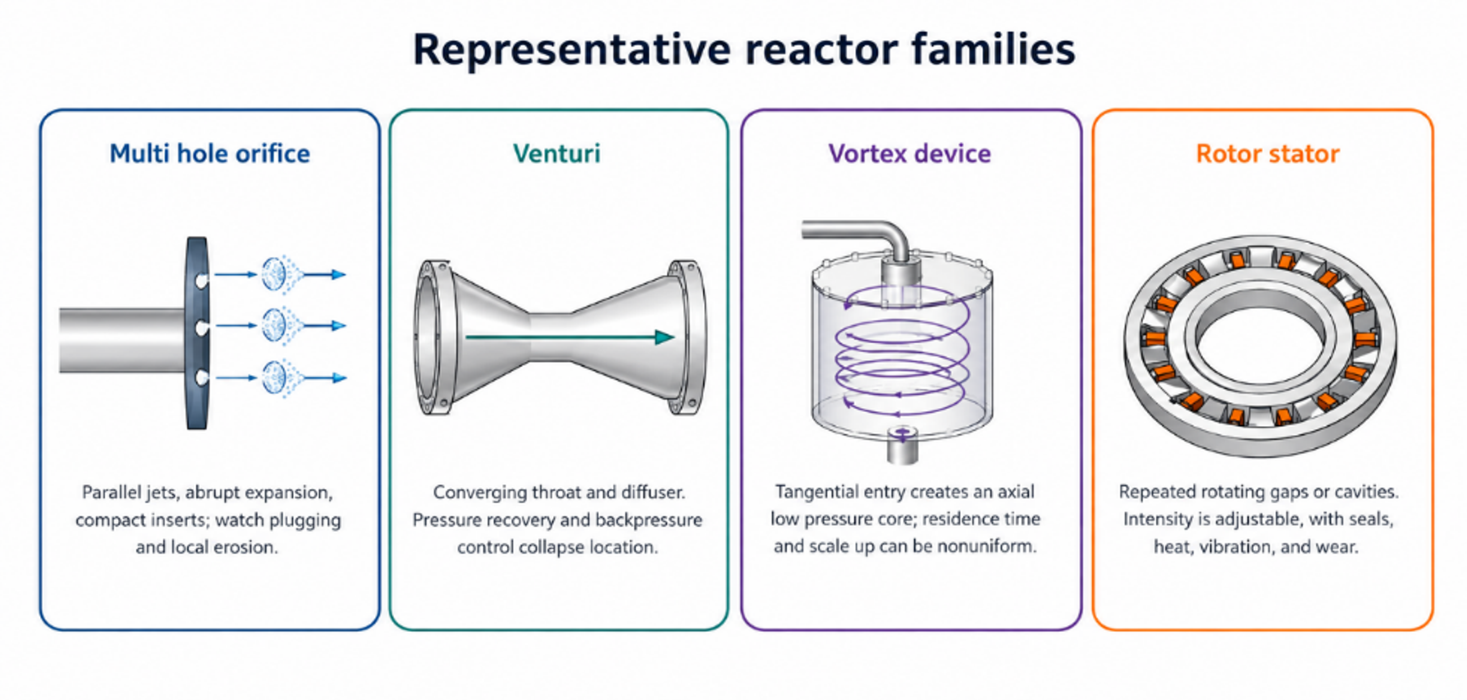
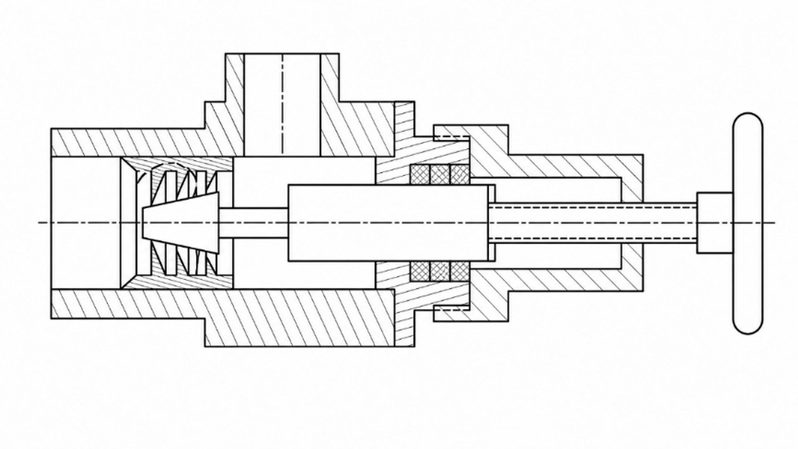
Table 3.1. Comparison of principal reactor families.
| Family | Low pressure mechanism | Advantages | Main cautions |
|---|---|---|---|
| Multi hole orifice | Parallel jets followed by abrupt expansion | Compact, interchangeable, and readily numbered up | Plugging, local erosion, broad residence distribution, and high pump load |
| Venturi | Converging section, throat, and diffuser recovery | Smooth recovery and continuous service | Longer body and sensitivity to diffuser angle and backpressure |
| Vortex device | Swirling core creates an axial low pressure zone | Extended cavity residence and no small parallel holes | Complex multiphase flow and difficult scale up |
| Rotor stator or SPR | Rotating gaps, cavities, slots, or teeth | Adjustable intensity and high throughput | Moving parts, seals, vibration, heat, and wear |
| Adjustable inline restriction | Movable throat and controlled recovery pressure | Can maintain a hydraulic fingerprint over changing flow | Proprietary characterization and need for site acceptance |
| Compression decompression reactor | Pressure increase followed by rapid controlled release | Can produce fine droplets and repeated pressure cycles | Cavitation may be promoted or intentionally avoided, depending on geometry |
3.4 Process architectures and treatment history
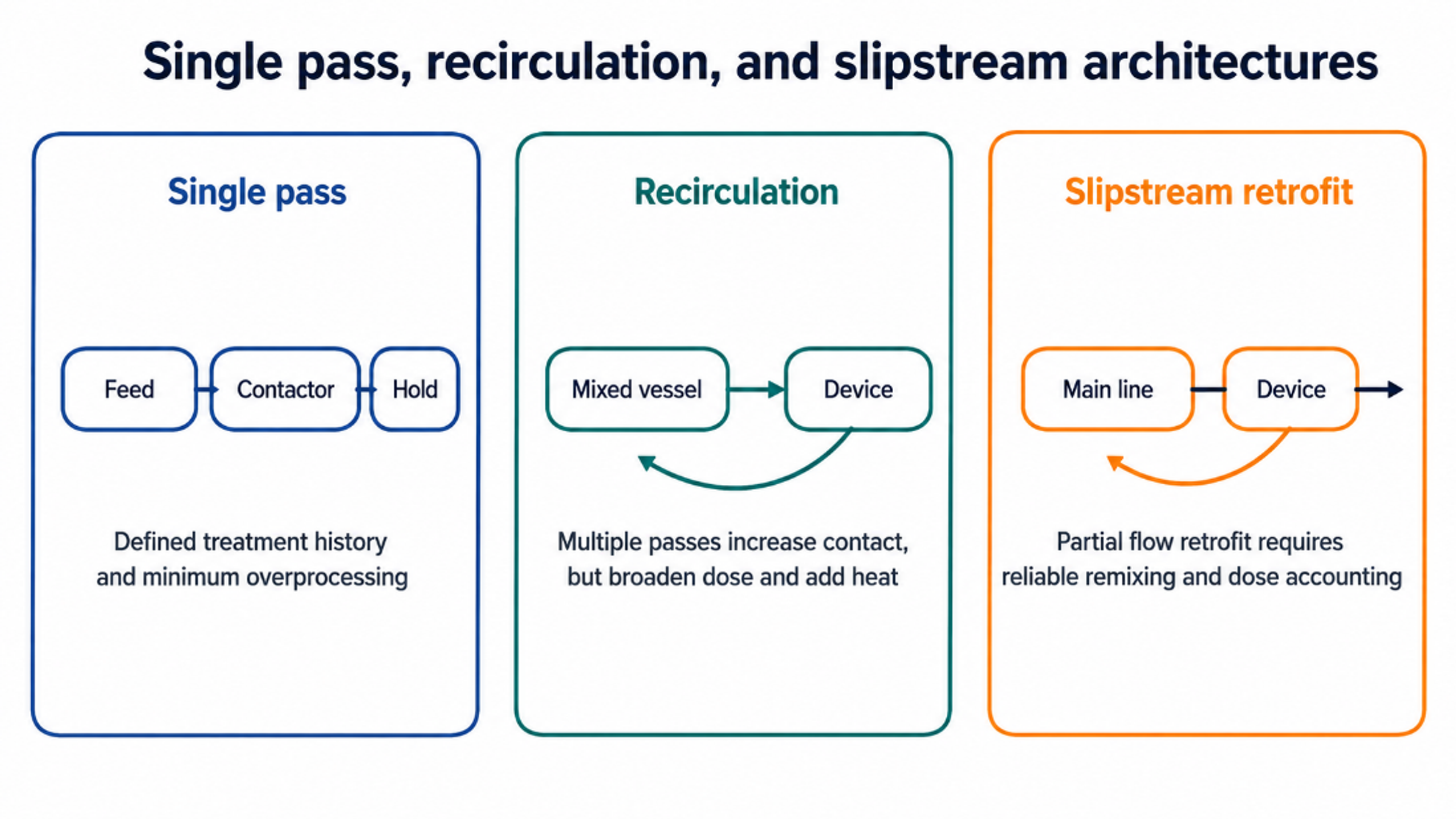
A single pass system provides the clearest treatment history and the lowest risk of overprocessing. Recirculation increases the number of contacts but broadens the distribution of passes: some material can receive many more exposures than the average. A slipstream retrofit treats only a fraction of the plant flow and therefore requires reliable mixing of treated and untreated material. Series reactors can create sequential pressure histories. Parallel reactors increase capacity but require flow balancing.
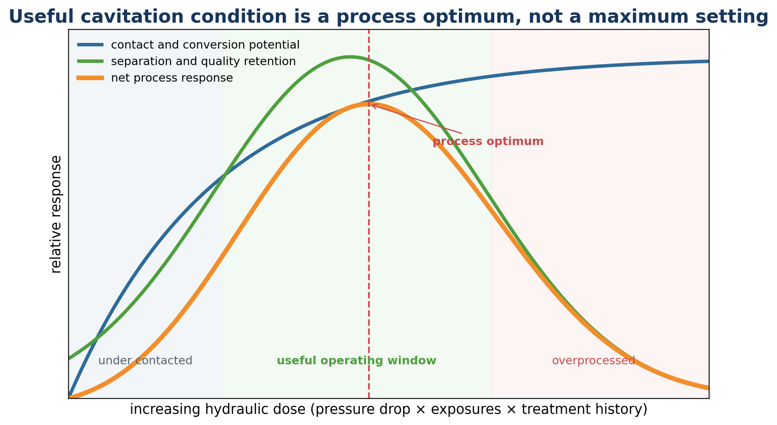
Increasing hydraulic dose does not guarantee increasing benefit. Contact and conversion generally improve at first, while separation, oxidation stability, temperature control, equipment life, and power consumption can deteriorate beyond an optimum. The useful setting is the lowest dose that reaches the chemical and separation endpoint.
4 Mechanisms of Process Intensification
4.1 Droplet breakup and interfacial area
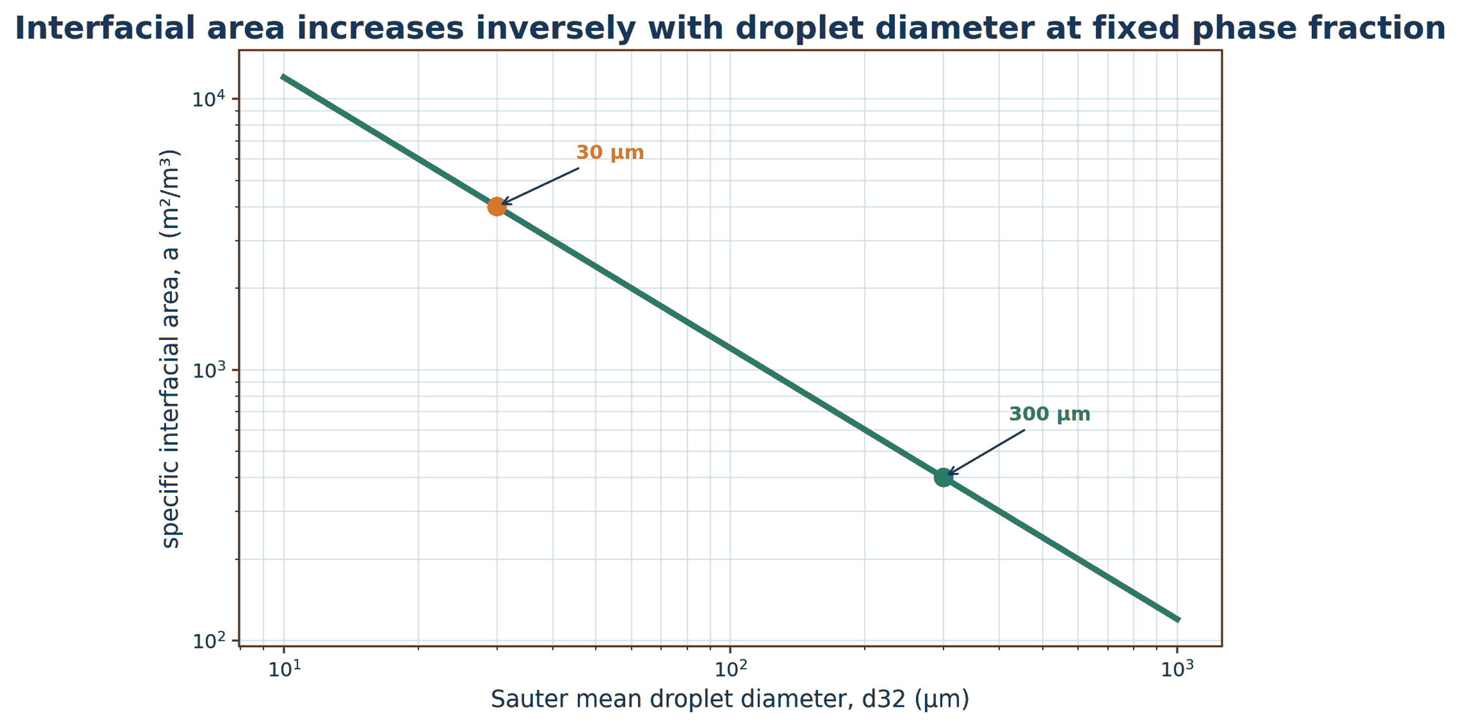
Most refining duties disperse a small aqueous phase into a continuous oil phase. For spherical droplets represented by Sauter mean diameter d32 and dispersed phase volume fraction phi, the specific interfacial area is approximated by:
Reducing from 300 micrometres to 30 micrometres increases interfacial area by a factor of ten at the same reagent dose. This geometric effect is the most direct explanation for rapid contact. It also explains the separation penalty: the same reduction produces droplets with lower settling velocity and much larger stabilizing surface.
A conceptual mass transfer rate can be expressed as (Equation 4.2):
Cavitation can increase both interfacial area and liquid side mass transfer coefficient by renewing the boundary layer. The equation remains useful even when reaction, adsorption, flocculation, and nonideal equilibrium occur simultaneously.
4.2 Stress criteria for breakup
Droplet deformation and breakup depend on the ratio of disruptive inertial or viscous stress to restorative interfacial tension. Three useful groups are:
The Weber number compares inertia with interfacial tension, the capillary number compares viscous stress with interfacial tension, and the Ohnesorge number reflects the role of dispersed phase viscosity. In turbulent breakup, a Hinze type estimate for maximum stable droplet diameter is:
The local energy dissipation rate varies strongly within a real reactor, so one average value cannot represent every droplet. Measurements should report the full droplet size distribution, not only a mean.
4.3 Micromixing and boundary layer renewal
A concentrated acid or caustic droplet can create a local reagent concentration far above the bulk average. Rapid deformation and boundary layer renewal distribute the reagent before undesirable side reactions dominate. In acid degumming this helps acid reach metal associated phospholipids. In neutralization it can reduce local caustic excess. In biodiesel it accelerates initial transfer of methoxide into the oil rich phase. The benefit is greatest when the initial limitation is interfacial transport rather than intrinsic chemistry.
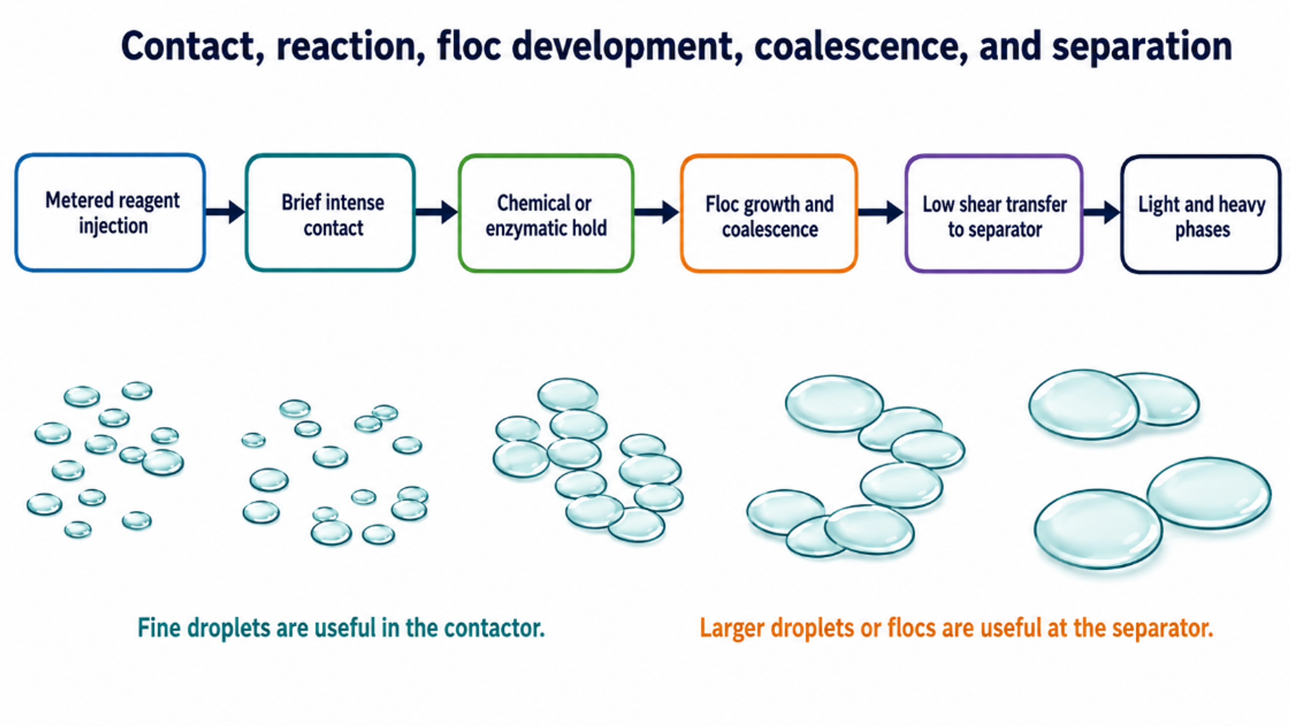
Collapse induced pressure pulses and liquid jets can also deagglomerate enzyme preparations, gums, and adsorbent particles. The downstream requirement may be the opposite: large, hydrated gum flocs, coalesced water droplets, separated glycerol, or filterable adsorbent cake. A useful system therefore creates a fine dispersion in the contactor and then deliberately permits phase growth downstream.
4.4 Residence time and recirculation
The nominal residence time () of a vessel is calculated using Equation 4.7:
For a well-mixed recirculation loop with liquid volume , the average number of passes during processing time t is:
These expressions do not capture bypassing, short circuiting, or the distribution of passes. Tracer testing is recommended when scale up depends on hold time or recirculation history. A nominal average of three passes does not mean that every fluid element receives exactly three contacts.
4.5 Heat, radical chemistry, and oxidation
Bulk heating lowers viscosity and can accelerate hydration, reaction, and separation. Excessive temperature can flash methanol, deactivate enzymes, reduce density difference, and accelerate lipid oxidation. In water rich microzones, cavity collapse can form reactive species. In unsaturated oil, the same chemistry can initiate peroxide formation and degrade tocopherols. The 2026 acoustic cavitation study by Kalenchak and coworkers provides a useful warning: fast neutralization was achieved, but oxidation markers were more favorable when the process was protected by nitrogen [14].
Oxidative verification should include peroxide value, p-anisidine value, conjugated dienes, total oxidation value where used, tocopherols, volatile aldehydes, and induction period. A reduction in phosphorus or reaction time that produces a meaningful loss of oxidative stability is not a successful outcome.
4.6 The emulsion paradox
The emulsion paradox is the dominant practical constraint. Reaction benefits from small droplets and high interfacial area. Separation benefits from larger droplets, low surfactant concentration, and limited turbulence. Phospholipids, soaps, partial glycerides, and some oxidation products stabilize interfaces precisely while impurities are being transformed. The design response is to use the minimum hydraulic dose, stop intense contact after the endpoint, provide a defined hold, reduce shear before the centrifuge, and evaluate droplet size at several locations.
Table 4.1. Mechanisms, expected benefits, measurements, and risks.
| Mechanism | Expected benefit | Measurement | Risk if excessive |
|---|---|---|---|
| Droplet breakup | Larger interfacial area and faster reagent contact | Droplet size distribution immediately after device | Persistent emulsion and poor separation |
| Boundary layer renewal | Higher volumetric mass transfer coefficient | Reaction time at equal reagent dose and endpoint | Continued contact after endpoint |
| Micromixing | Lower local reagent concentration peaks | Lower excess acid, base, enzyme, or catalyst | Neutral oil saponification or enzyme damage |
| Deagglomeration | Improved use of enzymes, gums, or adsorbent | Particle or floc distribution | Excess fines and high filter resistance |
| Pressure pulses and liquid jets | Rapid interface renewal and localized cleaning | Acoustic, vibration, and process response | Erosion, vibration, and noise |
| Bulk energy dissipation | Lower viscosity and faster kinetics | Motor power and temperature rise | Heat load, methanol loss, or oxidation |
| Reactive chemistry | Possible contaminant conversion | Oxidation and trace species markers | Lipid oxidation and shelf life loss |