
Technical publication
Back to publications
Reactors & equipment
Hydrodynamic Cavitation Technological Equipment
okozyuk.com
Published
Read complete publication for whole-document Find and printing. Browser Find and native printing on this reader include only loaded content.
6. Scale Up
Scale up is the translation of a validated hydrodynamic and product response state to a different throughput. It is not simply enlargement of every dimension. Cavitation is inherently multiscale: device dimensions set the mean pressure and velocity field, turbulence creates local pressure fluctuations, nuclei govern inception, cavities grow and interact, and collapse produces localized stress and chemistry. Changing scale alters several of these processes even when a small set of dimensionless groups is matched [2-4, 7-9].
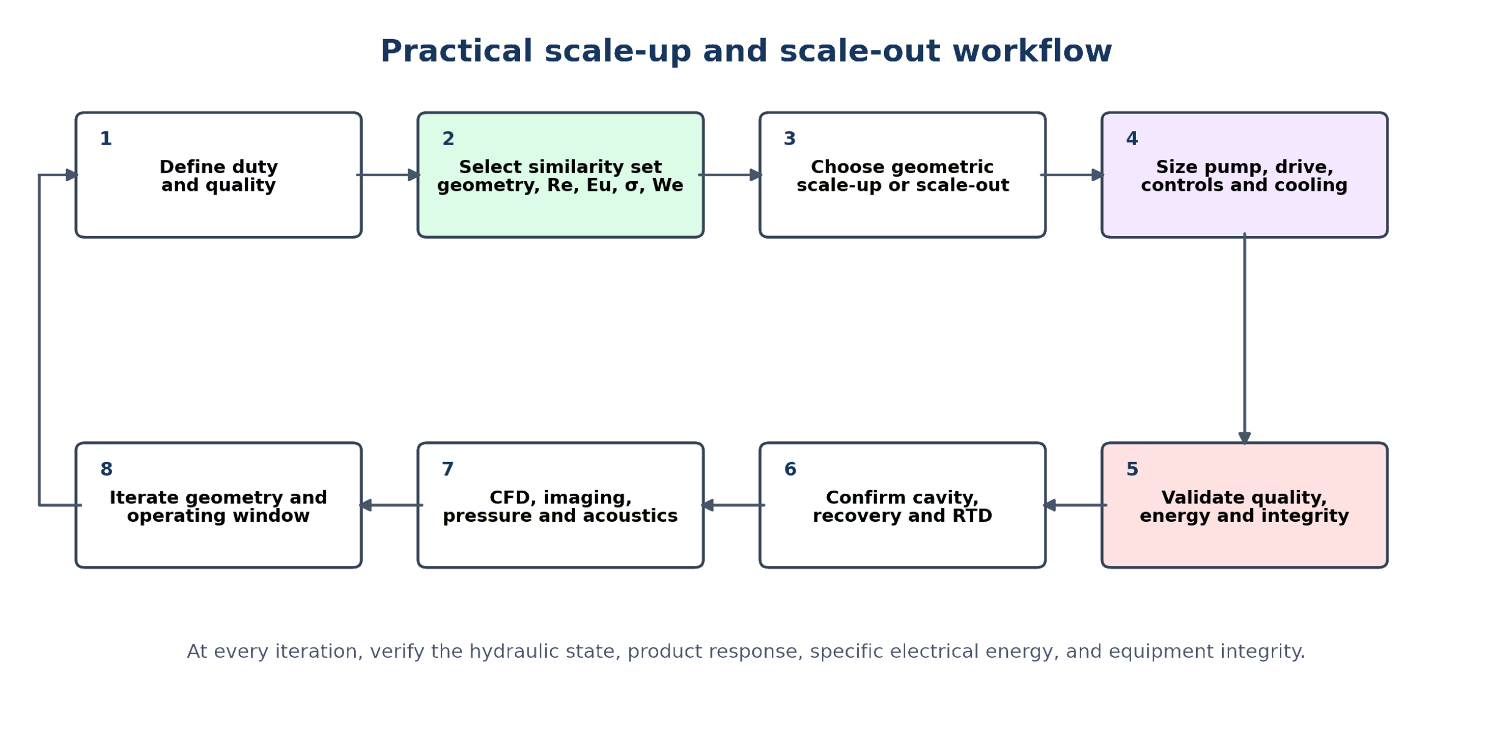
Figure 47. Practical scale up and scale out workflow for hydrodynamic cavitation equipment [58].
Geometric, flow, and pressure scale ratios may be defined as:
The subscript 1 denotes the reference device and 2 the target device. Geometric similarity would set all linear dimensions to , but this condition alone does not determine or . For a static device, preserving throat velocity implies Q proportional to area and therefore approximately squared. Preserving residence time in a geometrically similar chamber tends to require Q proportional to volume and therefore approximately cubed. These requirements conflict, illustrating why no single similarity rule preserves every relevant mechanism.
6.1 Static Device Scale Up
Orifice capacity can be increased by enlarging openings, increasing the number of openings, installing more stages, or operating parallel plates. Enlarging the hole changes cavity length, collapse distance, and the ratio of wall roughness to opening size. Increasing the number of identical holes preserves local jet geometry more closely but changes jet interaction and manifold uniformity. Parallel identical cartridges often provide the most conservative scale out route when a validated per hole condition must be preserved.
Venturi scale up should preserve converging and diffuser angles, throat aspect ratio, surface finish relative to throat size, and pressure recovery length. A larger throat may preserve velocity but increase cavity residence time and the absolute scale of turbulent structures. For vortex devices, geometric scale up has been demonstrated from about 1.3 to 248 L/min, but per pass degradation efficiency decreased with scale before approaching a plateau. Recent emulsification work found that geometric scale up and parallel scale out can maintain similar droplet size distributions while changing energy effectiveness. These observations support using both product quality and energy as independent scale criteria [3, 7-9].
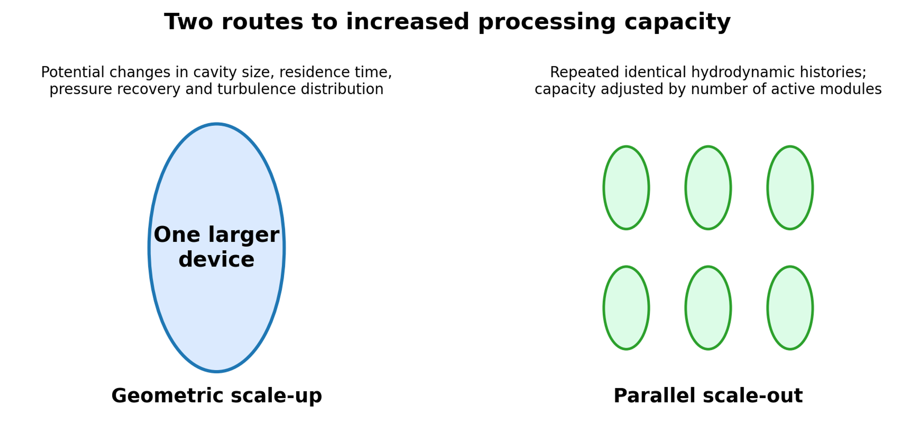
Figure 48. Two routes to increased capacity: geometric scale up [58].
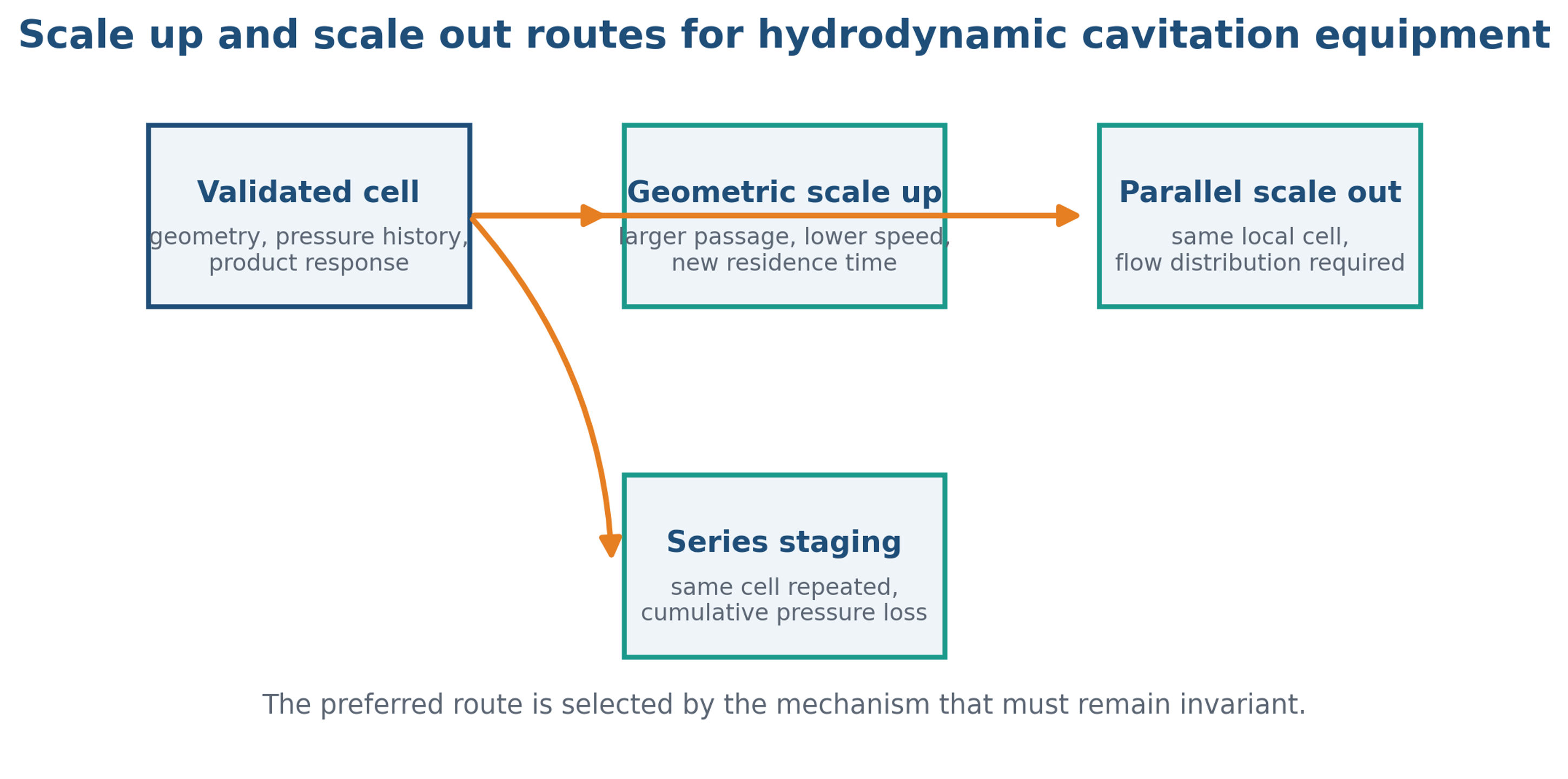
Figure 49. Scale up, scale out, and series staging routes for hydrodynamic cavitation equipment. Engineering decision diagram [58].
6.2 Dynamic Device Scale Up
Dynamic equipment introduces an additional constraint of rotating machine similarity. Classical pump affinity relations provide a first estimate for geometrically similar machines:
These relations apply most directly to noncavitating turbomachinery near similar efficiency and flow coefficient. Cavitation changes density, head, torque, and internal recirculation, so the relations are starting estimates rather than guarantees. Increasing diameter at constant speed raises tip speed and centrifugal stress. Holding tip speed constant requires speed to fall as diameter rises, which reduces passage frequency. Holding passage frequency constant increases tip speed. The scale up designer must therefore choose which mechanisms to preserve and verify the others experimentally.
A useful whole device power density metric is:
Vactive should be a clearly defined active volume, not the entire skid volume. Equal power density does not guarantee equal cavity collapse because the spatial distribution of dissipation may change. For rotor stator devices, gap ratio, pin or tooth count, rotor diameter, flow coefficient, inlet pressure, and vapor fraction should be included in the similarity set. Maintaining a very small absolute gap becomes mechanically difficult as diameter grows because thermal growth, runout, shaft deflection, and manufacturing tolerance consume the clearance budget [2, 3].
6.3 Per Pass Performance and Residence Time Distribution
For approximately first order transformation over n passes, a per pass coefficient may be estimated as:
Cn is concentration after n nominal passes. A constant kpass is an approximation; performance can decline as the easiest to transform fraction is depleted, temperature changes, gas accumulates, or the liquid properties evolve. Scale up studies should therefore compare the complete response versus pass number, not a single final conversion. Continuous flow systems should also report residence time distribution or a validated mixing model so that pass based laboratory data can be translated to industrial staging [3, 5].
6.4 Scale Effects, Viscosity, and Invariant Selection
Viscosity enters equipment scale up through the Reynolds number, through viscous pressure loss, through suppression of small scale turbulence, and through the time required for a cavity or dispersed phase interface to respond. A larger device can preserve nominal velocity while changing the ratio of boundary layer thickness to passage size. A more viscous liquid can therefore require a higher pressure difference for the same flow and can also weaken the central pressure depression in a vortex. These effects should be mapped experimentally rather than represented by an unpublished universal correction.
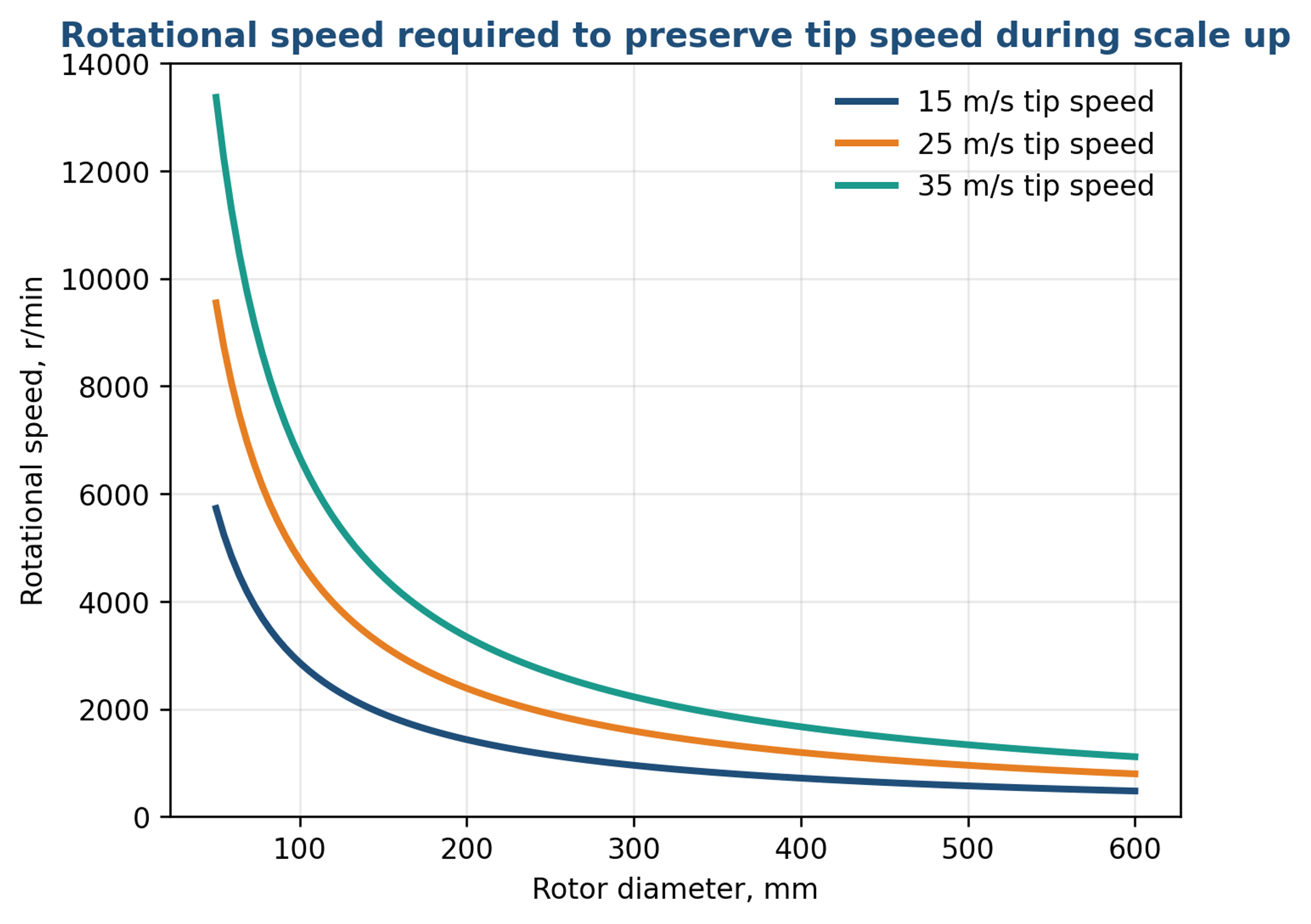
Figure 50. Rotational speed is required to preserve selected rotor tip speeds as diameter increases.
At constant tip speed, rotational speed falls inversely with rotor diameter. This preserves one velocity scale but lowers the frequency with which a liquid element encounters pins, teeth, or recesses. Preserving encounter frequency instead would require constant rotational speed and would increase tip speed and centrifugal stress as diameter grows. The design team must identify which mechanism controls product response and then verify the remaining mechanisms at pilot scale.
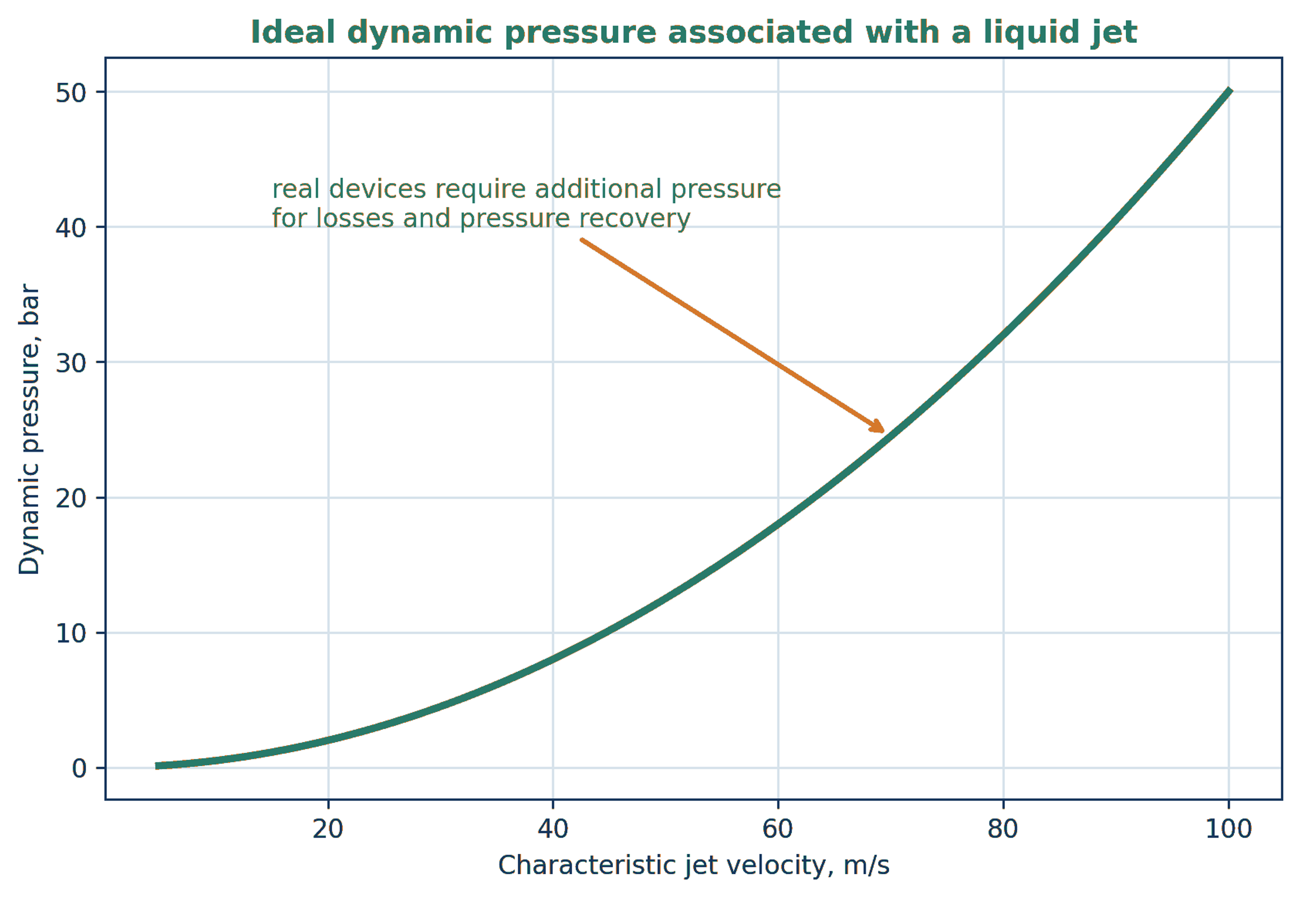
Figure 51. Ideal dynamic pressure associated with liquid jet velocity. The curve is a Bernoulli scale and does not include losses, vapor loading, or pressure recovery [58].
The velocity pressure relation provides a useful first estimate for static nozzles, interaction chambers, and impinging jets. Real equipment requires additional inlet pressure because friction, contraction, two phase flow, and recovery are irreversible. For high pressure homogenizers, the nominal pump pressure should therefore not be converted directly into a single cavity collapse pressure. A validated pressure history or controlled comparison is required.
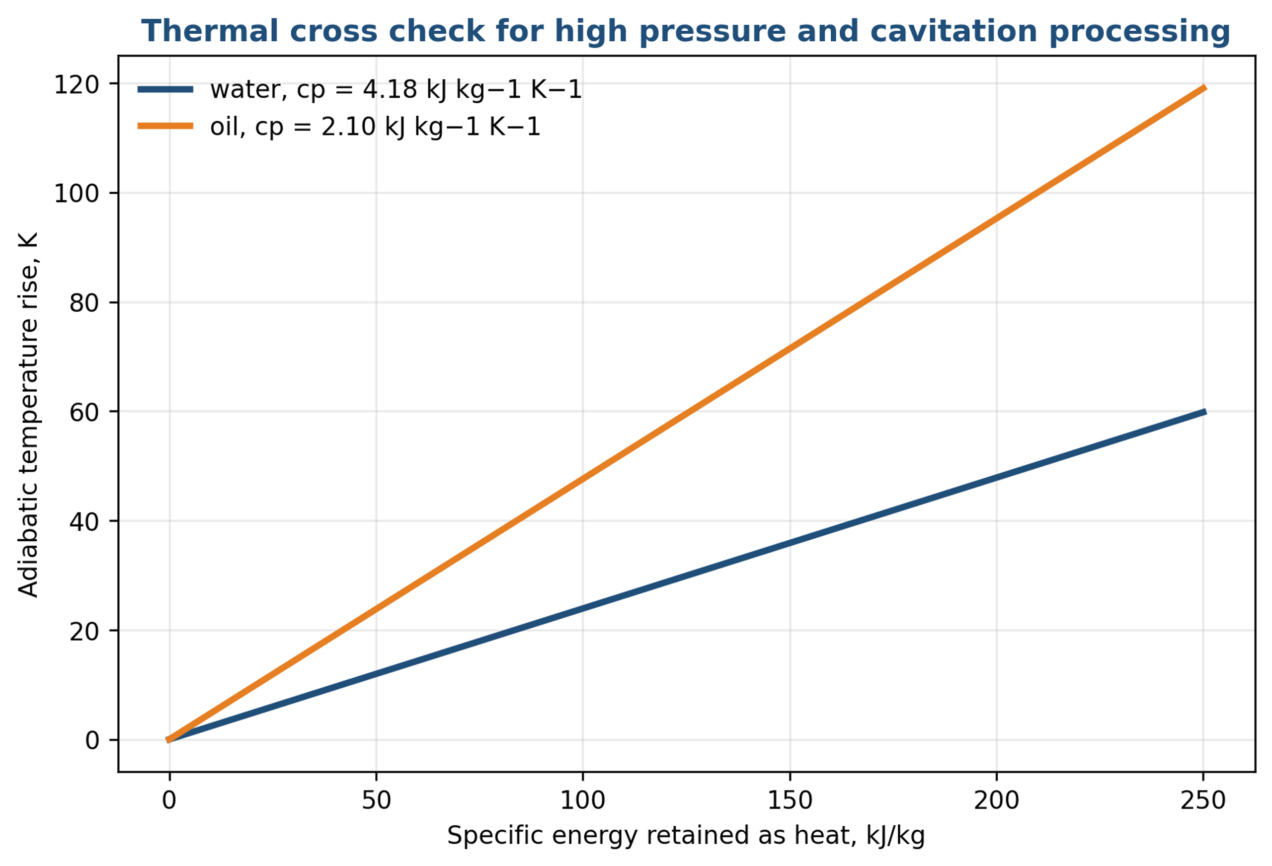
Figure 52. Adiabatic temperature rise if specific process energy is retained as sensible heat in water or oil [58].
Temperature rise is a practical cross check on the energy balance. Water requires about 4.18 kJ kg−1 for a one kelvin rise, whereas many oils require roughly half that energy. The actual outlet temperature depends on exposure time, metal heat capacity, heat exchange, recirculation, and phase change. A scale up test should compare both instantaneous outlet temperature and the total heat removed by the cooling system.
Table 16. Practical implications of scale dependent equipment behavior.
| Scale variable | What can change | Recommended control or test |
|---|---|---|
| Passage size | Boundary layer fraction, wall interaction, solids passage, and cavity residence time | Preserve local geometry where possible; otherwise map pressure and product response over the new size. |
| Rotor diameter | Tip speed, passage frequency, torque, stress, and active volume | State which invariant is selected and measure torque, vibration, and product distribution. |
| Viscosity | Reynolds number, pressure loss, turbulence, heat generation, and nuclei transport | Test representative viscosity at process temperature and include non-Newtonian behavior when applicable. |
| Backpressure | Collapse location, vapor fraction, choking, and outlet temperature | Control independently and record absolute pressure at defined stations. |
| Parallel branches | Flow maldistribution and unequal treatment dose | Balance resistance, instrument branches, and verify the worst branch. |
| Series stages | Cumulative pressure loss, heating, and gas accumulation | Measure stage pressures and temperature; provide drains and cleaning access. |
When parallel scale out is selected, the total capacity is:
Parallel trains preserve a validated local geometry but introduce manifold maldistribution. Each branch should have a balanced hydraulic resistance or a confirmed branch flow distribution, and the common pump must operate on a stable portion of its curve over the expected number of active trains.
6.5 Recommended Scale Up Program
A defensible program begins by freezing the product quality attributes and the energy boundary. The laboratory device is then mapped over pressure drop or speed, flow, backpressure, temperature, gas condition, and number of passes. A pilot device should be selected to test the most uncertain similarity assumption, not merely to increase volume. For a multihole orifice, that may be jet interaction; for a Venturi, diffuser recovery; for a vortex unit, chamber scale and core precession; for a rotor stator machine, clearance and tip speed effects.
Pilot scale up should require simultaneous agreement in hydraulic state, cavity regime, product distribution, temperature history, specific electrical energy, and equipment integrity. If one large device cannot reproduce the collapse environment, parallel scale out of identical validated devices should be evaluated. A scale out manifold must distribute flow uniformly, isolate failed branches, support cleaning, and allow the number of active modules to follow production demand. Scale out increases valves and branch controls but reduces the technical risk associated with a new internal flow regime [3, 7-9].
Table 17. Scale up and commissioning checklist.
| Step | Required evidence | Decision criterion |
|---|---|---|
| 1. Define duty | Feed envelope, target distribution or conversion, allowable temperature, contamination and erosion limits, production rate. | Clear quality attributes and test methods are agreed before equipment selection. |
| 2. Characterize reference unit | Complete geometry, Δp Q or torque speed map, inlet and outlet pressure, gas condition, electrical power, product response, uncertainty. | Reference operating window is reproducible over multiple runs. |
| 3. Select similarity priorities | Re, Eu, We, σ, tip speed, gap ratio, residence time, power density, cavity location, pass history. | The preserved and intentionally changed quantities are documented. |
| 4. Pilot test | Hydraulic state, electrical energy basis, product distributions, and erosion and fouling inspection. | Pilot reproduces both quality and SEC within specified tolerance. |
| 5. Choose scale up or scale out | Mechanical feasibility, manifold uniformity, maintenance, spare strategy, CAPEX and OPEX. | Route minimizes technical and lifecycle risk, not only installed cost. |
| 6. Factory verification | Water baseline, specified cavitating points, mechanical checks, and leakage checks. | Equipment satisfies the guaranteed operating envelope. |
| 7. Site verification | Actual feed, utilities, control logic, heat balance, sampling and cleaning validation. | Sustained production meets quality, energy, and integrity guarantees. |
6.6 Scale Up Conclusions
The most reliable scale up criterion is a hierarchy rather than a single number. First, preserve the geometry and local flow feature responsible for inception. Second, preserve the pressure recovery and collapse environment. Third, preserve the exposure distribution and product residence history. Fourth, verify the product distribution and specific electrical energy. Finally, confirm equipment integrity over a duration long enough to reveal erosion, fouling, seal wear, and contamination. Matching output quality without matching energy may be commercially unacceptable; matching energy without matching quality is technically irrelevant.