
Technical publication
Back to publications
Other
Engineering Calculations for Rotor-Stator Mixers
okozyuk.com
Published
Updated
Read complete publication for whole-document Find and printing. Browser Find and native printing on this reader include only loaded content.
13 Scale up and design limits
For geometrically similar equipment operating in a comparable flow regime at constant flow, pressure and power coefficients, the standard similarity relations are
These relations require similarity of geometry and operating regime. In practice, clearances, tooth thickness, motor speed and manufacturing tolerance frequently prevent exact geometric scaling. Constant tip speed requires , which changes feature passage frequency if feature count is fixed. Preserving nominal gap shear additionally requires to remain constant. Matching cavitation number requires a compatible absolute pressure and vapor pressure, while matching specific energy requires coordinated changes in power and throughput. These requirements impose distinct constraints and should be selected according to the process mechanism.
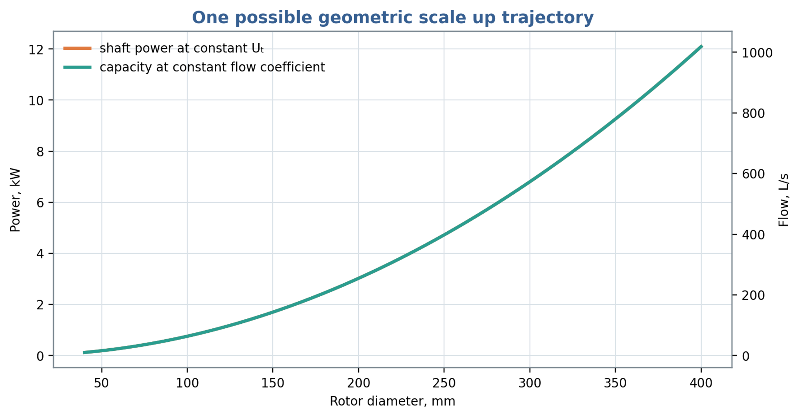
Figure 13.1. Illustrative scaling at constant tip speed, flow coefficient and power number. Under these assumptions, throughput and power both vary with the square of rotor diameter.
Table 13.1. Scale up criteria and quantities preserved
| Criterion held constant | Approximately preserves | Does not necessarily preserve |
|---|---|---|
| Tip speed | Rotor surface velocity | Pulse frequency, power density, cavitation number |
| Gap shear | Nominal viscous deformation rate | Turbulence, residence time, opening jets |
| Power per volume | Mean power input per specified volume | Local peaks, pressure, event frequency |
| Specific energy | Gross energy per processed mass | Stress distribution and thermal history |
| Cavitation number | Relative pressure margin | Nuclei population, gas content, pulse duration |
| Flow coefficient | Mean throughput similarity | Slot velocity if open area does not scale |
| Feature passage frequency | Number of periodic events per time | Tip speed and pumping capacity |
13.1 Selection of scaling criteria
Scale selection should follow the required process endpoint. Hall's original doctoral research compared emulsification at three mixer scales and across thirteen rotor and stator configurations. The author reported that tip speed combined with constant residence time was the most suitable basis for correlating mean droplet size across the investigated laboratory and factory equipment, including repeated passes. Stator opening area also affected power and emulsification within a single scale. These findings provide an experimental basis for selecting a practical scaling strategy, while retaining its formulation and geometry limits. Matching this pair of variables does not automatically preserve pulse frequency, gap shear, hydraulic pressure, cavitation margin or temperature rise, which require separate assessment [27].
Table 13.2. Selected experimental and computational evidence relevant to engineering scale up
| Study | Quantity investigated | Engineering implication and limit |
|---|---|---|
| James et al. [25] | Torque and power constants | Constants depend on the tested workhead and regime; verify corrected torque. |
| John et al. [15] | Batch and inline circulation | External throughput differs from internal exchange; match the flow definition. |
| John et al. [12] | Screen and inlet geometry | Controlled geometry changes support calibrated power and flow relations. |
| Hall et al. [23] | Emulsion droplet size | Formulation and local stresses limit transfer of specific energy correlations. |
| Håkansson et al. [24] | Local fragmenting stresses | Breakup location depends on the spatial and transient stress field. |
| Ayas et al. [11] | Viscoplastic liquid mixing | Constitutive behavior and local shear need explicit treatment. |
| Michael et al. [26] | CFD power and flow | A simplified preprint model retains substantial prediction uncertainty. |
| Hall [27] | Emulsification across scales | Tip speed with residence time was useful within the investigated systems. |
Mechanical and service requirements constrain the hydraulic scaling. Centrifugal stress and shaft deflection can affect the maintained gap; thermal expansion can reduce clearance; and cavitation or abrasive wear can change opening edges and discharge behavior. Cleaning requirements may also impose minimum accessible passage dimensions. Scale up should therefore proceed through hydraulic characterization, representative fluid testing, verification of heat removal and wear, and confirmation of the product endpoint over the intended operating envelope.
13.2 Workhead selection and geometric documentation
The photographs in Figure 13.2 and Figure 13.3 illustrate the range of screen forms that can be fitted around a rotor. Their relevance to engineering calculation lies in the opening dimensions, edge thickness, accessible clearance and inlet arrangement. A screen designation should therefore be accompanied by its measured geometry when comparing power, circulation and product response [28].
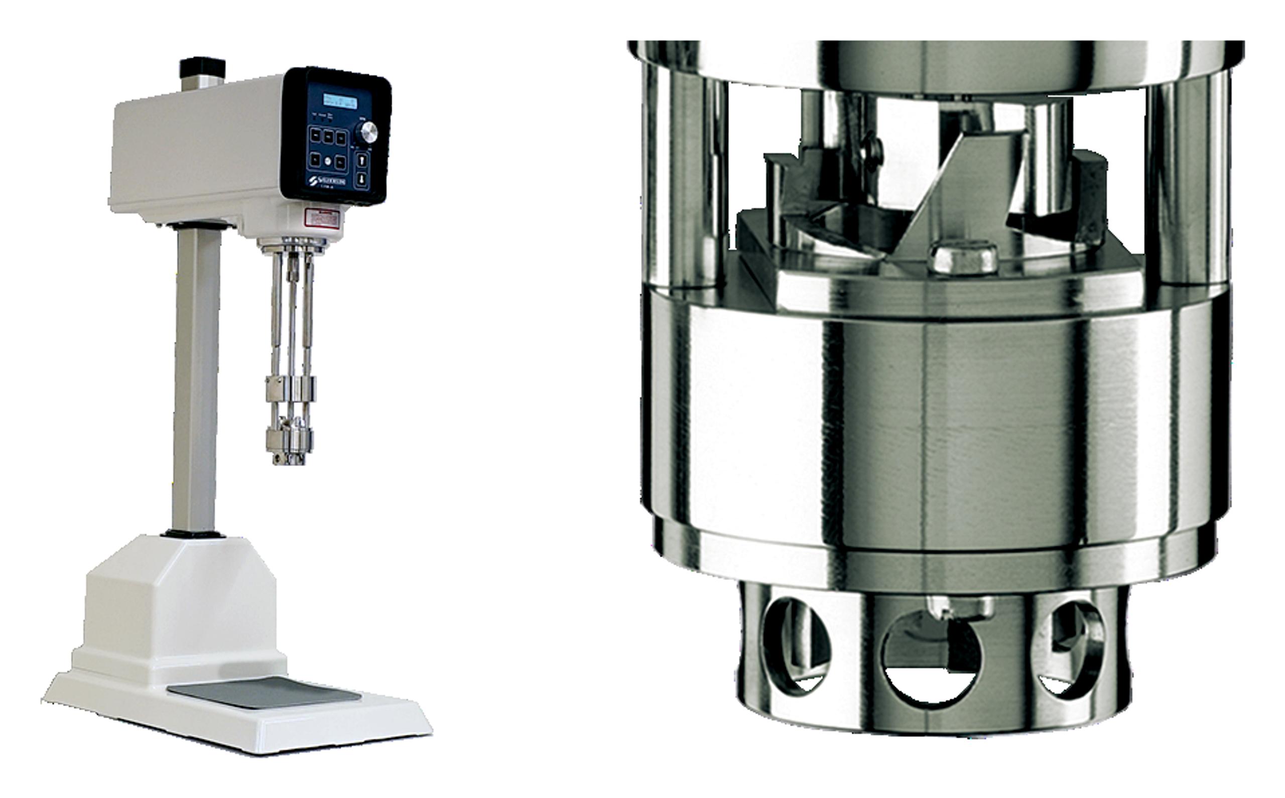
Figure 13.2. Representative laboratory mixer and a close view of its working head. Photographs from Silverson technical literature [28].
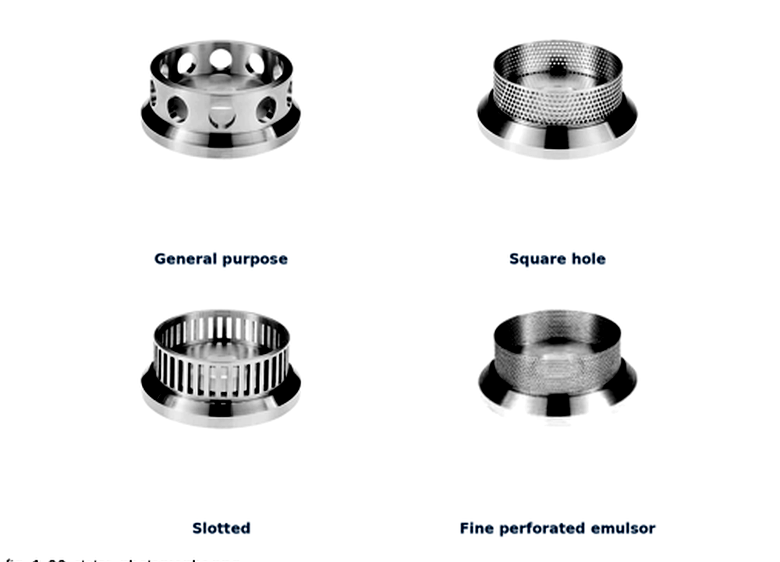
Figure 13.3. Examples of commercial stator screens with general purpose, square hole, slotted and fine perforated configurations. Photographs and screen designations from Silverson technical literature [28].