
Technical publication
Back to publications
Reactors & equipment
Cavitation Driven Exfoliation of Graphene and Two Dimensional Materials
okozyuk.com
Published
Read complete publication for whole-document Find and printing. Browser Find and native printing on this reader include only loaded content.
4 Cavitation Physics and Force Transmission
4.1 Pressure Reduction and Cavitation Number
Hydrodynamic cavitation begins when local static pressure approaches the liquid vapor pressure or when dissolved gas and heterogeneous nuclei expand under reduced pressure. A simplified Bernoulli relation illustrates the coupling among static pressure, velocity, and elevation:
p is static pressure, ρ is liquid density, u is mean velocity, g is gravitational acceleration, z is elevation, and hL represents irreversible head loss. While rigorous modeling of real cavitating flows requires advanced two-phase Eulerian-Eulerian or mixture frameworks coupled with turbulence closures, simplified scaling parameters remain invaluable for preliminary design intuition. The intensity of cavitation is primarily governed by the dimensionless cavitation number ():
σ is the cavitation number, is a reference upstream or local pressure, is vapor pressure, ρ is density, and u is the selected reference velocity. Lower σ generally indicates stronger cavitation, but geometry and nuclei distribution affect the observed regime.
A constriction does more than reduce pressure. It accelerates particles, generates high velocity gradients, changes platelet orientation, creates turbulent eddies, and can focus collisions at walls or channel junctions. The pressure recovery zone determines where bubbles collapse. Collapse within a controlled chamber can transfer useful mechanical energy to particles, whereas collapse in a pump, valve seat, or downstream pipe primarily promotes erosion rather than exfoliation.
4.2 Bubble Dynamics
The radial behavior of an isolated spherical bubble in an infinite liquid is commonly represented by the Rayleigh-Plesset equation. Although this relation does not fully describe a bubble cloud adjacent to a flake, it identifies the principal roles of pressure, density, viscosity, surface tension, gas content, and time:
R is bubble radius, Ṙ and R¨ are radial velocity and acceleration, pB is pressure inside the bubble, p∞ is far field pressure, μ is dynamic viscosity, γ is surface tension, and ρ is liquid density.
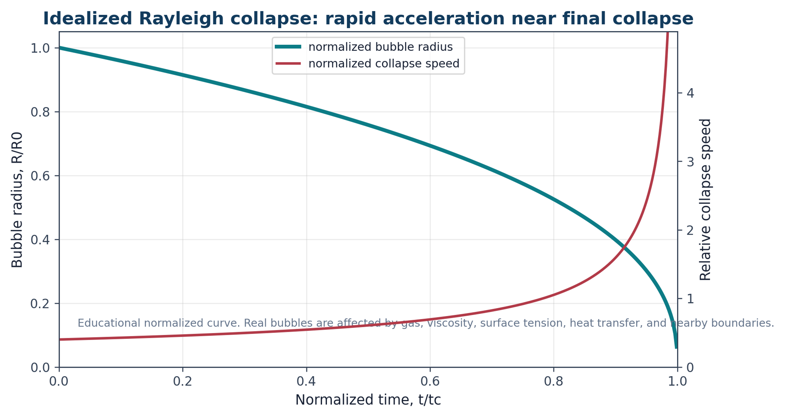
Figure 4.1. Normalized educational representation of rapid bubble collapse. Collapse velocity increases strongly near the final stage, which helps explain intense local pressure pulses [37].
Practical exfoliation occurs within bubble clouds, near solid surfaces, and in particle laden flow. Synchronized collapse of a bubble cloud can produce a pressure pulse greater than that associated with an isolated bubble. High speed and X-ray free electron laser imaging reported in [17] showed that quasi simultaneous cloud collapse can generate shock waves that interact with two dimensional materials on nanosecond time scales. These observations support both immediate fracture and fatigue accumulated through repeated pressure pulses.
4.3 Stress Pathways in Layered Particles
Several mechanical pathways operate simultaneously. A compressive wave entering a particle can reflect from a particle liquid interface as a tensile wave and promote separation. A bubble collapsing near a surface can form an asymmetric microjet. Velocity gradients impose viscous shear, turbulent fluctuations impose Reynolds stress, and particle collisions or wall impacts introduce bending and edge damage. Pressure retained within defects or liquid filled galleries can be released when the surrounding pressure decreases. Repeated pulses can extend cracks even when an individual event remains below the threshold for complete separation [7-12,17]. The characteristic shear rate is determined by the velocity difference across a gap or boundary layer and the effective gap thickness:
γ̇ is a characteristic shear rate, Δu is the velocity difference across a gap or boundary layer, and is the effective gap thickness. The viscous shear stress () for a Newtonian approximation is given by:
τ is viscous shear stress for a Newtonian approximation. Concentrated graphite dispersions may be non-Newtonian, so apparent viscosity at the process shear rate should be used.
Re is Reynolds number and Dh is hydraulic diameter. In particle laden and cavitating flow this value is a scaling indicator, not a complete description of turbulence or two phase structure.
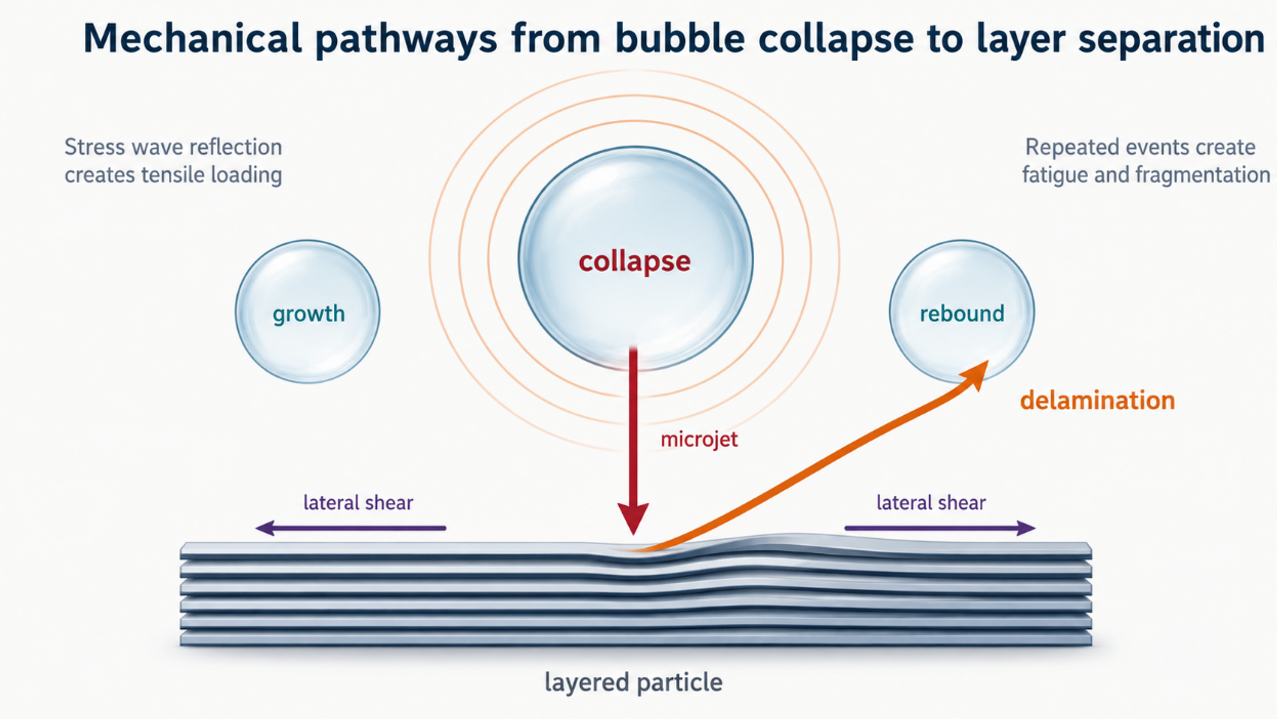
Figure 4.2. Mechanical pathways by which bubble collapse, pressure waves, microjets, lateral shear, and repeated fatigue can separate or fragment layered particles [7-12,17].
Table 4.1. Mechanisms contributing to cavitation assisted exfoliation.
| Mechanism | Primary loading direction | Useful effect | Possible damage or limitation |
|---|---|---|---|
| Stress wave reflection | Normal to the basal plane or particle surface. | Opens preexisting cracks and separates adjacent layers. | Can fracture brittle flakes or create holes when impulse is excessive. |
| Microjet impact | Localized normal and tangential loading. | Initiates peeling at edges, folds, or surface defects. | Highly localized damage and equipment erosion. |
| Viscous shear | Parallel to adjacent layers. | Promotes interlayer sliding and continuous delamination. | Cuts large flakes when stress or exposure is excessive. |
| Turbulent Reynolds stress | Fluctuating lateral and normal loading. | Repeated random loading over the particle population. | Broad product distribution when residence time is broad. |
| Particle collision | Impact, bending, and edge loading. | Creates fresh edges and assists self-exfoliation. | Introduces fragmentation, contamination, and abrasion. |
| Pressure release in galleries | Normal expansion from internal liquid or gas. | Can open intercalated or defect rich structures. | Requires wetting and may produce uncontrolled expansion. |
| Fatigue from repeated passes | Repeated subcritical normal and lateral stress. | Raises exfoliation fraction without one extreme event. | Defect accumulation, heating, stabilizer degradation, and diminishing returns. |
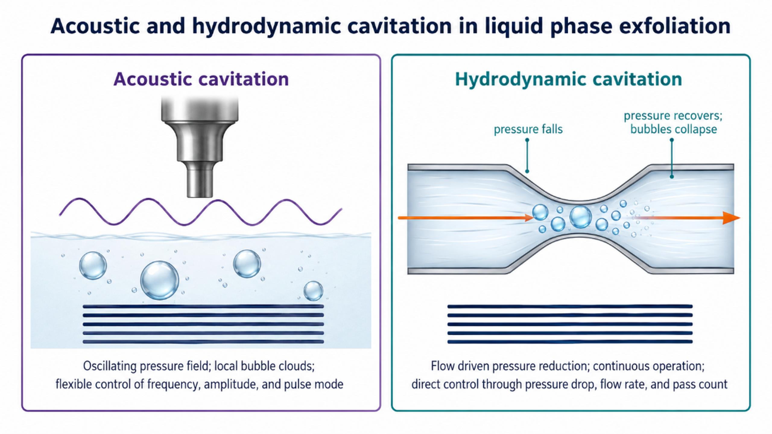
Figure 4.3. Comparison of acoustic and hydrodynamic cavitation fields. Both create bubbles and collapse events, but the field geometry, residence time, and scale up variables differ [37].