
Technical publication
Back to publications
Reactors & equipment
Anti-Cavitation Control Valves
okozyuk.com
Published
Read complete publication for whole-document Find and printing. Browser Find and native printing on this reader include only loaded content.
Abstract
Cavitation in liquid control valves results from local pressure reduction below vapor pressure followed by vapor collapse during pressure recovery. The associated microjets, pressure waves, vibration, and unsteady hydraulic forces can cause trim erosion, pressure boundary damage, noise, loss of control authority, and reduced service life. This article presents a unified engineering treatment of cavitation physics, liquid valve sizing parameters, pressure recovery behavior, and anti-cavitation trim architecture. The discussion relates cavitation indices and liquid choking criteria to practical design strategies, including staged pressure reduction, opposed jet bubble isolation, stacked disk and concentric sleeve trims, axial multistage geometries, multipath trims, dirty service configurations, and fixed energy dissipators. Material selection, seat protection, outlet velocity, actuator stability, solids tolerance, and system layout are examined as coupled design variables. Application considerations are summarized for water distribution, power generation, oil and gas, petrochemical, and low flow injection services. A worked sizing example demonstrates preliminary severity assessment, choked flow capacity, stage count estimation, and hydraulic power dissipation. The article also reviews field diagnosis, maintenance, computational fluid dynamics, patent development, topology optimization, and additive manufacturing. Final valve selection should be based on the complete operating envelope and tested coefficients for the specific valve and trim geometry. Keywords: cavitation; control valves; anti-cavitation trim; pressure staging; liquid choking; valve sizing; severe service.
12. Conclusions
Anti-cavitation control valves function by managing the pressure and velocity history of the liquid through the entire pressure-reduction process. The central design objective is to prevent a single local restriction from producing an uncontrolled pressure minimum followed by strong recovery near a vulnerable surface. This objective can be achieved through staged pressure reduction, flow subdivision, progressive area increase, frictional dissipation, impingement, tortuous passages, protected seats, enlarged galleries, and appropriate system layout. [1-15]
The principal engineering conclusions are as follows:
-
Cavitation is governed by local instantaneous pressure, nuclei, residence time, and pressure recovery, not only by the overall pressure drop.
-
Flashing and liquid choking must be identified separately because their flow and damage mechanisms differ.
-
Sigma, , , , , and are useful only when their definitions, pressure locations, travel, and vendor test basis are consistent.
-
Severe service usually requires multistage pressure reduction. Stage resistance should be allocated to keep later stage velocity and pressure excursions under control.
-
Opposed jets can protect trim in mild service by moving collapse into the fluid core, but they do not necessarily eliminate cavitation.
-
Seat protection, strong guidance, actuator stiffness, and body gallery design are as important as the nominal number of stages.
-
Fine passages are compact and effective for clean service. Dirty service requires large continuous passages, protected seats, and credible particle data.
-
Hardened materials extend life but cannot compensate for a fundamentally incorrect pressure profile.
-
Final selection requires all operating cases, installed piping effects, tested vendor coefficients, scale effects, noise and vibration assessment, and maintainability.
-
CFD, additive manufacturing, and topology optimization can improve capacity-specific trim designs, but these methods require experimental validation and manufacturing qualification. [1-32]
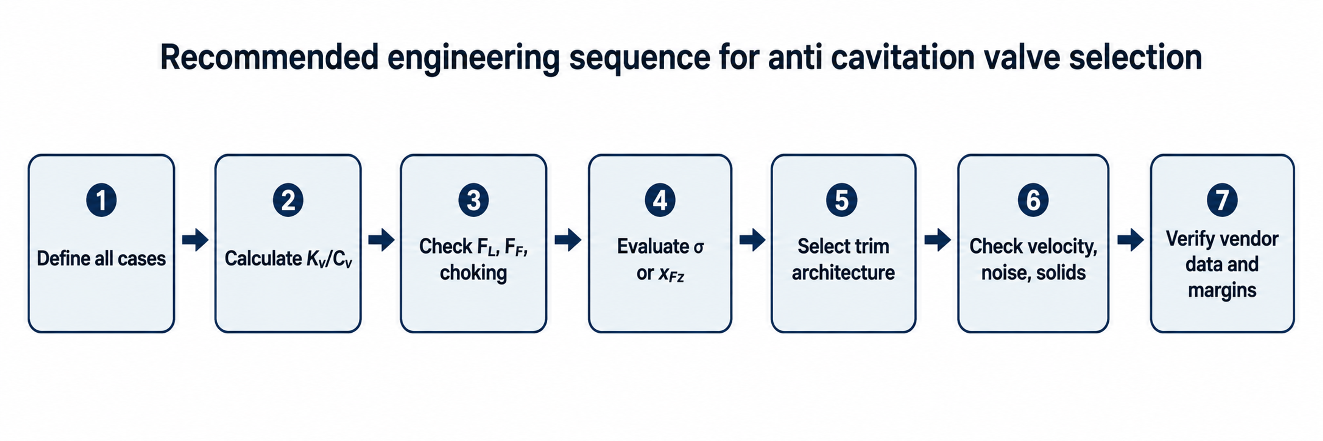
Figure 40. Recommended engineering sequence from process definition to verified selection.