# Performance considerations in stator selection for high shear rotor-stator mixers
## Abstract
Stator geometry is a primary process variable in high shear rotor-stator mixing because it governs hydraulic restriction, discharge area, local velocity gradients, and the frequency of shear generating passage events. These effects directly influence pumping capacity, pressure drop, energy dissipation, recirculation, solids tolerance, fouling tendency, and final dispersion quality. This article reviews the process implications of common stator geometries, including coarse disintegrating, square hole, slotted, fine screen, and multistage or toothed heads. Stator selection should therefore be treated as a first order engineering decision tied to process objective, rheology, and scale up path.
## 1. Introduction
In high shear rotor-stator mixers, stator aperture geometry is one of the primary design variables governing hydrodynamic performance and process outcome. The stator does far more than contain the rotor. Its opening pattern determines the hydraulic restriction surrounding the rotating element, the effective discharge area, the magnitude and distribution of local velocity gradients, and the frequency with which fluid elements are subjected to intense shear and extensional deformation.
As a result, stator design directly influences several coupled performance variables: volumetric pumping rate, pressure drop across the head, local energy dissipation rate, recirculation intensity, solids passage capability, and susceptibility to fouling or blinding. Commercial systems commonly use four baseline stator geometries: coarse disintegrating heads, square hole screens, slotted heads, and fine emulsor or fine screen heads. More aggressive configurations may incorporate toothed stators or multistage slotted ring assemblies to increase the number of shear zones and breakup events experienced during a single pass through the work head.
From an engineering standpoint, the stator pattern changes the balance between pumping and comminution. Coarse disintegrating heads typically provide lower hydraulic resistance, higher bulk circulation, and better tolerance for large particles or fibrous solids, but they generate fewer high intensity shear events per pass. Square hole and slotted heads impose greater restriction, increase local discharge velocity through the apertures, and promote stronger shear driven dispersion. Fine emulsor heads push this effect further by maximizing repeated fluid acceleration, deceleration, and reorientation across small openings, which improves droplet and particle size reduction at the expense of throughput, solids tolerance, and ease of cleaning.
In practical process terms, moving from a coarse disintegrating head to a square hole, slotted, or fine screen geometry shifts machine behavior along four key axes: throughput capacity, local shear intensity, solids handling robustness, and cleanability. For that reason, stator selection should be treated as a first order process design decision rather than a secondary mechanical detail.
## 2. Effect of stator geometry on process behavior
### 2.1 Coarse disintegrating heads
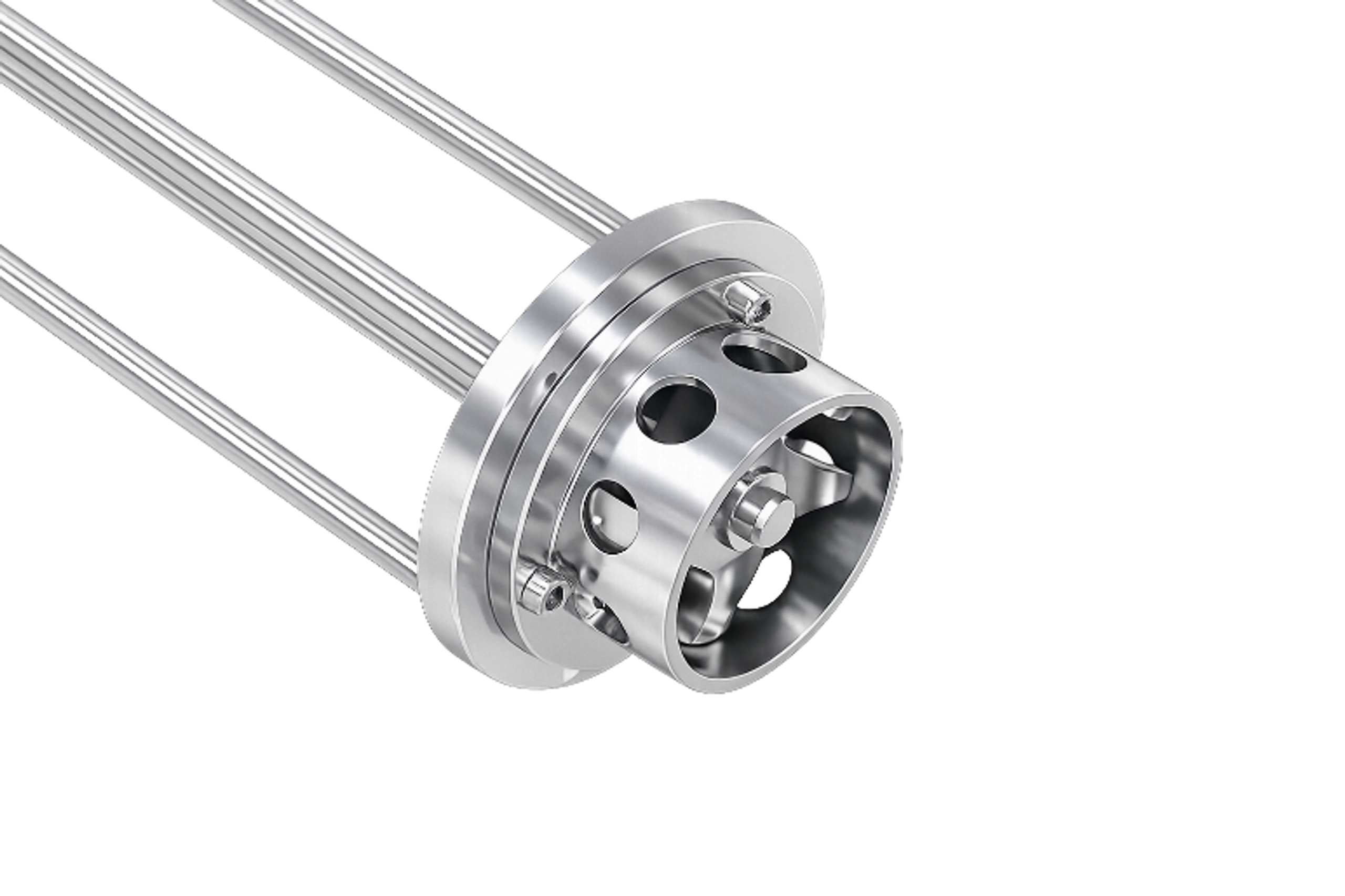
Coarse disintegrating head rotor-stator assembly
A coarse disintegrating head is a high flow rotor-stator geometry intended for primary size reduction, rapid phase turnover, and first pass incorporation of solids, semi solids, and difficult powders. The stator is typically drilled or slotted with relatively large openings, often circular or square, which increases open area and reduces hydraulic restriction through the head. In practical terms, this geometry shifts performance toward bulk pumping capacity, strong recirculatory exchange, and mechanical breakup of larger agglomerates rather than maximum shear intensity at a very small gap.
From an engineering standpoint, this head sits at the throughput dominant end of the rotor-stator spectrum. The larger stator apertures reduce pressure drop and allow higher volumetric flow through the work head at a given rotor tip speed. That makes it effective where the process objective is to move a large mass of product through the shear zone quickly, repeatedly expose fresh material to the rotor-stator interface, and prevent localized overprocessing. It is commonly selected for early stage duty such as powder induction, wet out of low density solids, hydration of gums or thickeners, dispersion of soft solids, and breakdown of semi solid feed materials before finer processing.
Its value is strongest in processes with large initial particle size, strong phase viscosity mismatch, or a requirement for rapid tank turnover. The coarse head handles demanding premix conditions well because it tolerates higher solids loading, is less prone to immediate blinding than fine screens, and can sustain circulation even when the system is still nonuniform. In liquid-liquid service, it is useful for pre-emulsification where the immediate need is gross droplet breakup and phase incorporation rather than final droplet size minimization.
The main limitation is shearing density. Because the fluid passes through larger openings, the head generates lower local energy dissipation rates and fewer high intensity shear events per unit volume than a fine disintegrating or emulsor screen. As a result, it is generally not the optimum final stage head when the process target is fine emulsion, narrow particle size distribution, smooth finished texture, or maximum interfacial area development. In most engineered mixing trains, the coarse disintegrating head is best viewed as a front end conditioning tool: it prepares the material for subsequent refinement by a finer rotor-stator head or by a downstream homogenizing step.
### 2.2 Square hole screens
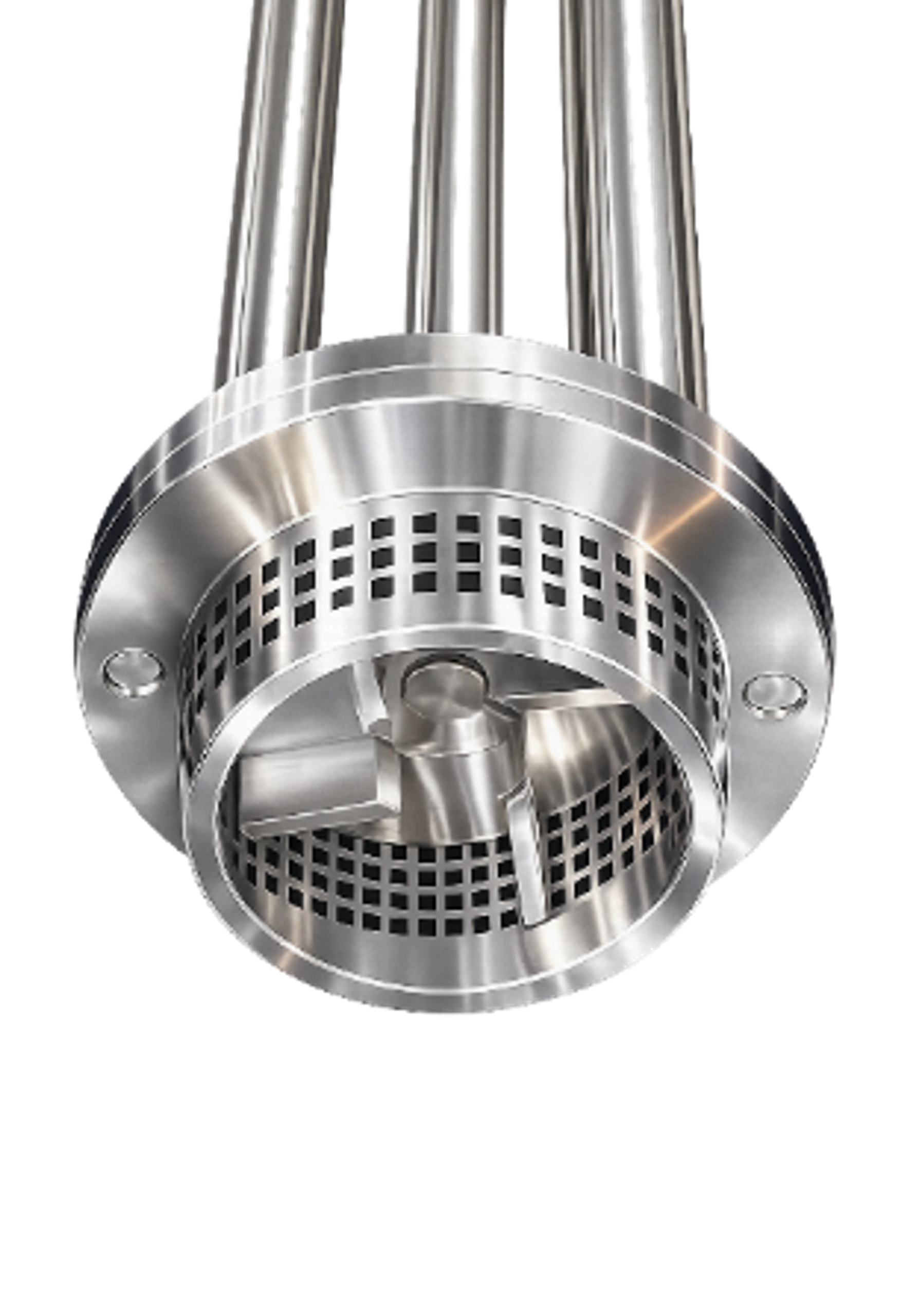
Square hole screen rotor-stator assembly
A square hole high shear screen is a stator geometry used in rotor-stator mixing systems when the duty requires high local energy dissipation, repeated extensional and shear deformation, and aggressive recirculation through the work head. In operation, the rotor generates strong suction into the head, accelerates the fluid solid mixture to high tip speed driven velocities, and forces it through a dense array of square apertures. Each passage through the rotor-stator clearance and each discharge through the stator openings creates a new shear event, so the product experiences multiple high intensity deformation cycles in rapid succession.
From a process engineering standpoint, this screen is typically the general purpose high shear stator for demanding dispersion and homogenization service. It is well suited for rapid deagglomeration of powders, dissolution of soluble granular materials, size reduction of insoluble particles, and formation of fine emulsions, gels, and colloidal suspensions. The dense perforation pattern increases the frequency of particle rupture, agglomerate breakdown, and droplet disruption events compared with a coarser stator. That usually translates into narrower particle or droplet size distribution, faster solids incorporation, and improved uniformity of the final product.
The tradeoff is hydraulic. A finer, denser square hole screen imposes greater flow resistance, increases pressure drop across the head, and typically reduces throughput at a given rotor speed and power input relative to a coarse screen. It also raises the risk of localized plugging or blinding when the feed contains long fibrous material, tough elastic fragments, or poorly wetted powders that can form paste like accumulations at the apertures. For that reason, square hole heads are most effective when the feed is reasonably flowable, solids are introduced in a controlled manner, and the formulation does not contain components likely to bridge or smear across the openings.
In practical selection terms, the square hole screen is usually chosen when the primary objective is shearing intensity and dispersion quality rather than maximum pumping rate. It is a strong choice for emulsification duty, powder liquid incorporation, and general particle size reduction where the process benefits from repeated high energy forcing events and where the system can tolerate the associated increase in hydraulic load.
### 2.3 Slotted heads
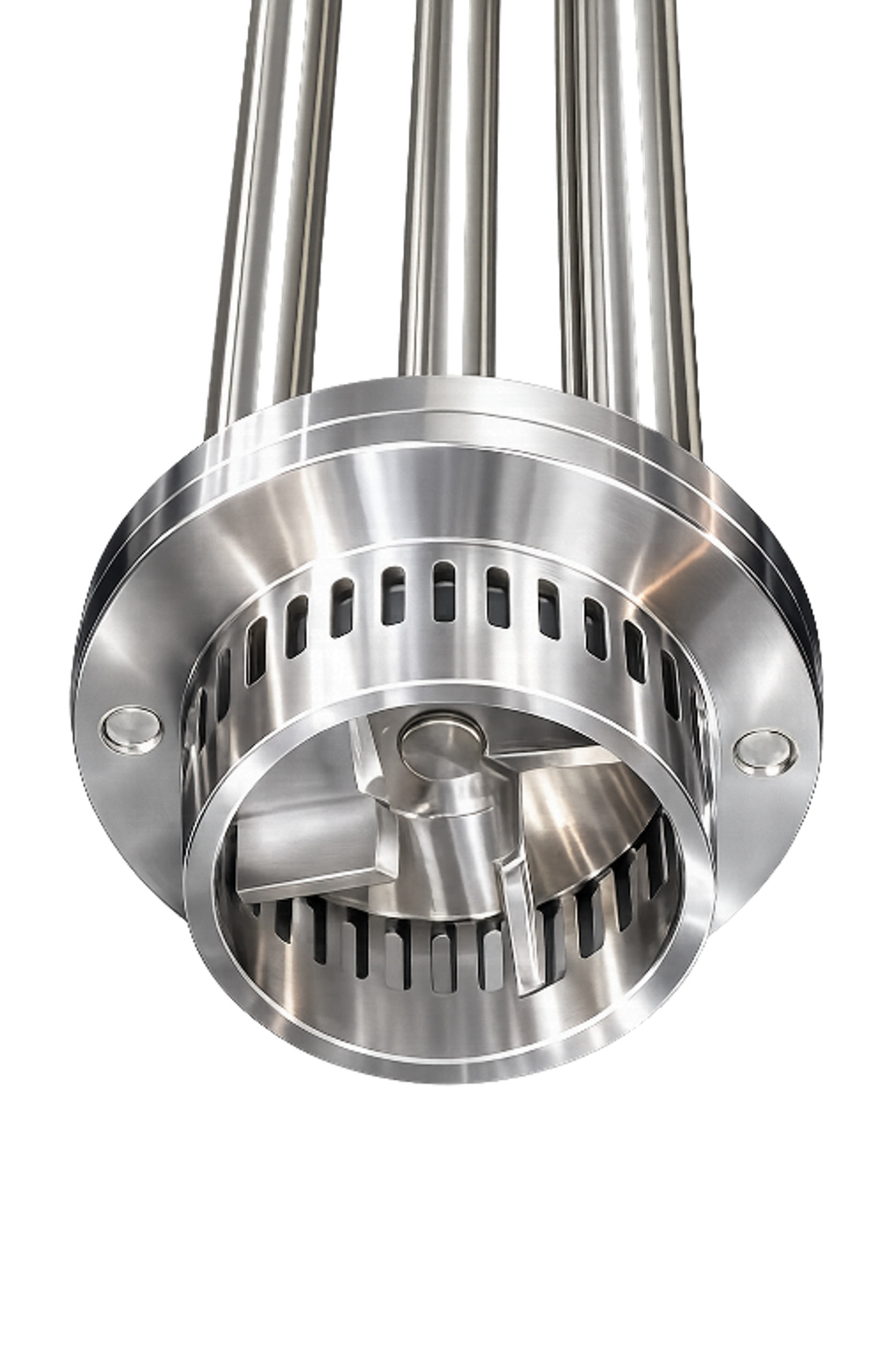
Slotted head rotor-stator assembly
A slotted disintegrating head is a rotor-stator high shear mixing element engineered for aggressive size reduction, dispersion, and homogenization of difficult feedstocks, especially those that are fibrous, deformable, viscoelastic, or tissue like. Typical duty includes the breakdown of animal and vegetable tissue, the comminution of stringy or cellular solids, and the progressive disintegration of elastic materials such as rubbers and some polymers. The working principle combines high tip speed rotor action with close clearance passage through a stator fitted with elongated vertical slots. This geometry generates strong local velocity gradients, repeated acceleration deceleration cycles, hydraulic shear in the rotor-stator gap, and direct mechanical shearing as particles, fibers, or soft solids are drawn into the shear zone and forced across the slot edges.
From a process engineering standpoint, the slotted stator is often the preferred geometry when the formulation contains materials that would tend to blind, bridge, or wrap on fine perforations. The elongated slot profile presents a lower plugging risk than small round holes while still maintaining a high energy shear field at the slot entrance, within the gap, and at the slot discharge. This makes the design more tolerant of long fibers, connective tissue, peel, skins, pulp, and other non-free flowing solids. In practical terms, slotted heads usually provide a more favorable pumping to shear balance than fine screen emulsor heads: they recirculate material effectively, sustain throughput under solids loading, and still deliver substantial particle reduction. For that reason, they are widely used in both batch and inline configurations where the objective is rapid disintegration, solubilization, and prehomogenization of challenging materials before finer downstream shear treatment or final polishing.
### 2.4 Fine screen or emulsor heads
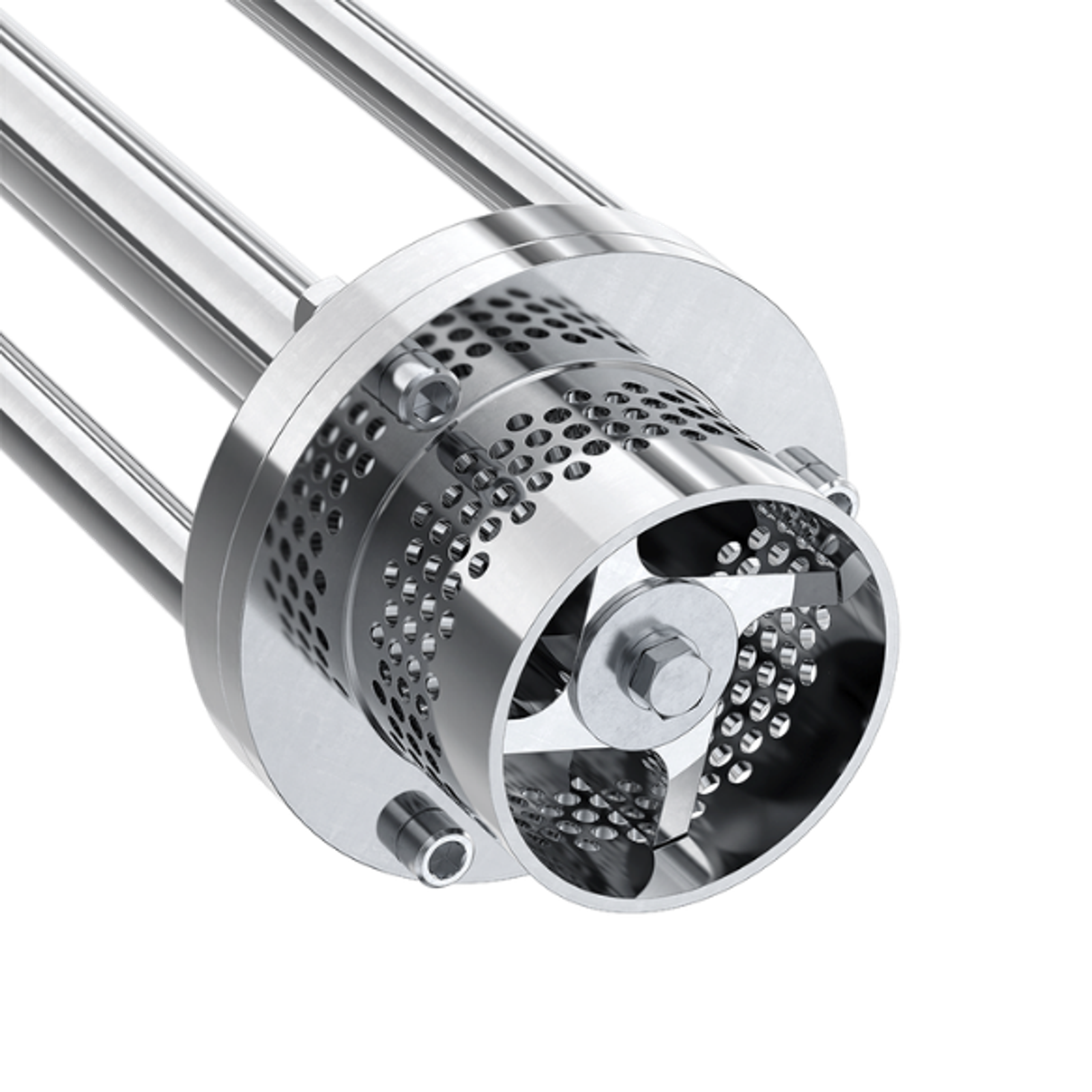
Fine screen or emulsor rotor-stator assemblySource: Mixer Direct
A fine screen rotor-stator homogenizer is a high shear finishing device designed for late stage droplet and agglomerate size reduction, texture refinement, and emulsion polishing. Unlike broader slot or coarse toothed stator geometries that are more forgiving during early dispersion, the fine emulsor uses a stator with very small apertures or a fine perforated screen. This geometry sharply increases local velocity gradients as product is accelerated through the restricted openings, producing intense shear, extensional deformation, and hydraulic impact at the discharge zone.
From a process standpoint, this is typically a finishing geometry rather than a front end dispersion tool. The reduced opening size increases discharge velocity and raises the energy density applied to the fluid element during the final pass through the stator. That added shear can drive further droplet breakup, collapse soft agglomerates, and improve final particle size distribution, gloss, mouthfeel, or surface smoothness. In emulsification duty, it is often the stage that determines whether the product reaches the target fineness and visual uniformity.
Its effectiveness depends heavily on feed condition. A fine screen performs best when the material has already been premixed, prewetted, and stripped of large solids or poorly dispersed lumps. If coarse particles, stringy solids, or partially hydrated gums are introduced too early, the screen becomes a restriction point rather than a refinement stage. Under those conditions, flow rate drops, shear becomes nonuniform, temperature rise may increase, and the risk of fouling, plugging, or unstable power draw goes up significantly.
This geometry is also more viscosity sensitive than more open stator designs. As viscosity rises, the pressure required to force product through small openings increases, and effective circulation can fall off quickly. That makes fine screens better suited to low to moderate viscosity systems, or to process windows where viscosity remains manageable until the finishing step. In practice, fine emulsor are selected when final quality targets justify tighter hydraulic restriction, but they should usually be paired with an upstream dispersing stage that conditions the product before it reaches the screen.
### 2.5 Multistage and toothed heads
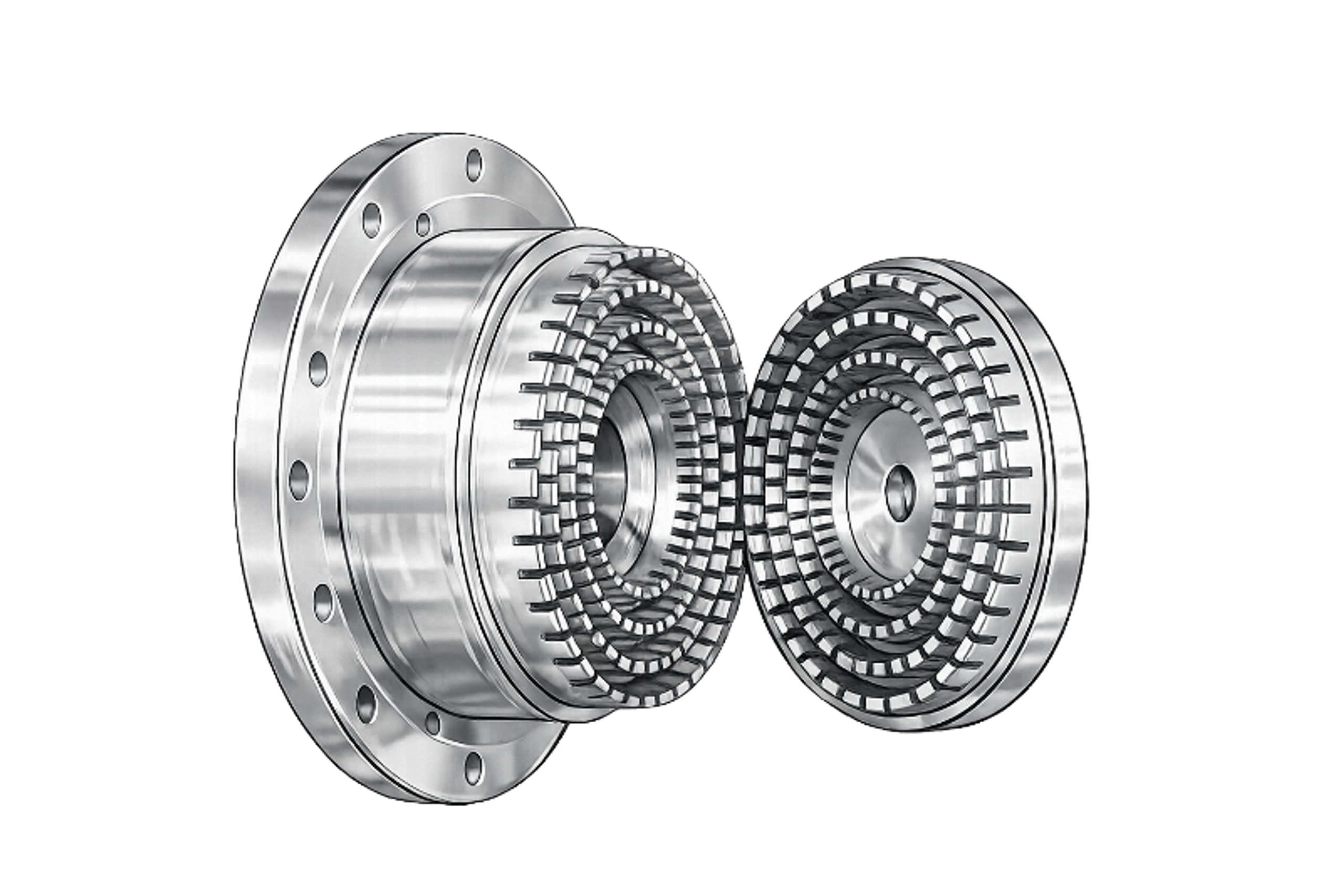
Multistage toothed rotor-stator homogenizer
A multistage toothed rotor-stator homogenizer is an intensive mechanical dispersion device used when the process objective is fine droplet size reduction, deagglomeration, or tightly controlled emulsification. In contrast to a single stage rotor-stator head, multistage design forces the product through two or more successive shear zones during one pass through the work head. Each stage imposes another cycle of acceleration, gap shear, pressure fluctuation, turbulence, and discharge, so the material experiences repeatedly controlled breakup before it leaves the head.
From an engineering standpoint, the value of a multistage head is not just higher instantaneous shear rate. The more important benefit is staged energy application. Larger droplets, soft agglomerates, or partially wetted solids can be broken down in the first zone, then exposed to finer and more uniform disruptive stresses in downstream zones. This improves droplet size distribution, reduces the number of bulk recirculation passes needed to reach specification, and usually gives better batch to batch repeatability than relying on a single high shear event alone.
Toothed and specialized stator geometries extend this principle further. Instead of using only simple slots or holes, these heads use interacting tooth profiles, fine shear gaps, and multiple concentric rotor-stator interfaces to generate localized extensional flow, high velocity gradients, and repeated tooth passing events. The result is stronger mechanical disruption of droplets and particle clusters, especially in systems where interfacial tension is high, solids are difficult to wet, or the formulation tends to recoalesce after initial breakup.
These configurations are usually selected for duties where final microstructure matters more than maximum flow rate. Typical drivers include narrow droplet size targets, improved emulsion stability, pigment or powder deagglomeration, and processes where downstream performance depends on consistent particle size distribution. The tradeoff is that multistage and toothed heads generally impose higher power draw, greater hydraulic resistance, and more heat generation than simpler heads, so motor sizing, residence time, temperature control, and CIP cleanability have to be considered during equipment selection.
## 3. Stator selection as a function of viscosity
### 3.1 General framework
Viscosity is one of the primary screening variables in rotor-stator mixer selection because it controls the relationship between local shear generation inside the work head and bulk material transport through the vessel. As viscosity rises, the governing process constraint typically shifts from shear intensity to hydraulic throughput and batch turnover. A stator geometry that performs well in low viscosity emulsification may become ineffective in a high viscosity cream or gel simply because fresh material is no longer renewed at the rotor-stator zone at a sufficient rate. For engineering selection, viscosity should therefore be treated not as an isolated formulation property, but as a variable that affects four coupled process parameters:
where: is rotor tip speed, is rotor diameter, is rotational speed, is the characteristic shear rate in the rotor-stator gap, is rotor-stator gap width, is the rotor-based Reynolds number, is fluid density, is dynamic viscosity, is power per unit volume, is power draw, and is batch volume.
These relationships provide a practical framework for stator selection. At low viscosity, Reynolds number is high and inertial effects support strong pumping through relatively restrictive stators. At medium viscosity, the process becomes a balance between shear generation and pressure loss across the stator. At high viscosity, the dominant limitation is usually circulation, not peak local shear.
### 3.2 Governing engineering considerations
#### 3.2.1 Shear rate
Rotor-stator mixers generate very high local shear rates because the fluid is accelerated through a narrow gap and repeatedly discharged through stator openings. The approximate gap shear rate scales with tip speed and inversely with the rotor-stator clearance:
This quantity is useful for comparing local kinematic intensity, but it does not by itself predict batch performance. A high calculated shear rate can coexist with poor process efficiency if the volume of material actually passing through the head is too low.
#### 3.2.2 Pressure drop across the stator
As stator openings become finer, the available open area decreases and hydraulic resistance rises. This increases the pressure drop required to sustain a given flow through the head. In practical terms, finer stators increase local stress and jet velocity, but they also reduce throughput. The tradeoff becomes more severe as viscosity increases. This is the key reason why fine emulsor heads are often excellent finishing tools in low viscosity systems yet become poor first pass tools in high viscosity service.
#### 3.2.3 Reynolds number regime
The rotor based Reynolds number provides a practical indicator of whether the work head is operating in a predominantly inertial or viscous regime:
At high Reynolds number, turbulence, rotor-stator passage events, and discharge jets dominate dispersion and emulsification. At lower Reynolds number, viscous drag becomes more important, the pumping ability of the head declines, and material transport through the stator becomes increasingly restrictive. While rotor-stator devices are more geometrically complex than simple impellers, the Reynolds number still provides useful process guidance:
- high : stator selection can focus more aggressively on shear geometry
- intermediate : stator restriction must be balanced against turnover
- low : the system becomes circulation limited and auxiliary agitation often becomes necessary
#### 3.2.4 Tip speed and scale transfer
Tip speed is one of the most important transfer variables for rotor-stator systems because it directly sets characteristic local velocity and strongly influences gap shear rate. However, scale up should not be based on rotational speed alone. Two systems operating at the same RPM but with different rotor diameters will generate different tip speeds and therefore different local stress fields. For this reason, constant tip speed is usually a better first pass scale up criterion than constant RPM:
Even so, constant tip speed alone is not sufficient for rigorous scale up. Stator geometry, open area, residence time in the work head, power density, vessel shape, and macrocirculation pattern all influence final process outcome.
### 3.3 Viscosity-dependent stator selection
#### 3.3.1 Low viscosity systems
Low viscosity systems include water like liquids, solvent based blends, and light syrups. In this regime, the rotor-stator head can generally self-pump efficiently, and pressure loss across fine stator openings remains manageable. Reynolds number is relatively high, so inertial transport, discharge jets, and repeated stator passage events support efficient deagglomeration and emulsification. Under these conditions, finer stators are technically attractive because they increase shear event frequency and discharge velocity without causing excessive flow choking. This makes them well suited for droplet size reduction and fine dispersion duty. From an engineering standpoint, low viscosity systems are usually shear limited rather than circulation limited. The design question is therefore centered on how much local stress intensity and how many disruptive passage events are needed to achieve the target particle or droplet size. Fine emulsor stators are preferred when the process objective is final droplet refinement. Square hole stators are often preferred when the duty includes both dispersion and emulsification. Coarse heads remain useful when rapid turnover, blending, or powder incorporation is more important than final fineness.
#### 3.3.2 Medium viscosity systems
Medium viscosity systems include heavy syrups, pourable creams, suspensions, and structured liquids. This is the range in which stator selection becomes a true compromise between local shear intensity and hydraulic throughput. At these viscosities, fine stators can still generate high local shear, but the pressure drop across the stator begins to reduce circulation significantly. As a result, part of the batch may experience excellent local treatment while overall vessel turnover becomes inadequate. This is often the practical limit of relying on a single restrictive stator geometry for the entire process. The problem becomes more pronounced for non-Newtonian materials. In a shear thinning formulation, the apparent viscosity inside the rotor-stator gap may fall sharply, but the bulk phase may remain much more viscous. That means the work head can process what reaches it very effectively while still failing to renew untreated material from the rest of the vessel at an adequate rate. For this viscosity range, slotted and square hole stators are typically the most versatile options. Slotted geometries are especially useful for polymers, gums, fibers, and elastic phases because they are less prone to blinding and permit better passage of partially structured material. Square hole stators are often selected for general deagglomeration and emulsification where some restriction is acceptable but strong overall circulation must still be maintained. A staged process is frequently the best engineering solution. A coarse or slotted head can be used first for incorporation and macro uniformity, followed by a square hole or finer stator for finishing.
#### 3.3.3 High viscosity systems
High viscosity systems include creams, pastes, ointments, gels, and high solids concentrates. In this regime, the primary process constraint is usually not insufficient local shear but insufficient material transport. Even with high tip speed, a fine stator may only process a limited active zone if bulk material cannot be brought continuously to the work head. In such cases, the mixer produces strong local treatment but poor batch scale homogenization. Heat generation may also become localized, and stagnant regions may form away from the head. For high viscosity duty, stator selection must be approached as part of a combined macromixing and high shear system. The rotor-stator head provides localized shear, but bulk exchange is typically maintained by anchor agitators, scrapers, or other low speed vessel sweeping devices. Without such assistance, the rotor-stator head may not achieve acceptable turnover. Coarse and slotted stators are generally preferred as primary geometries in this range because they reduce flow restriction and preserve throughput. Fine emulsor stators may still have value, but usually only as a late stage finishing step once the formulation is already sufficiently homogeneous and mobile.
### 3.4 Scale up implications
Rotor-stator scale up should preserve the process mechanism, not just the nominal machine setting. In practice, that means identifying whether the duty is dominated by local shear, by repeated stator passage events, by circulation rate, or by a combination of these.
A practical engineering scale up hierarchy is:
1. Preserve the process objective, such as emulsification, deagglomeration, wet out, or homogenization
2. Preserve the most relevant dynamic quantity, typically tip speed and, where necessary, power per unit volume
3. Preserve the circulation pattern and residence time distribution through the workhead
4. Adjust stator geometry if viscosity dependent hydraulic restriction changes with scale
This point is important. A lab mixer and a production mixer may operate at the same nominal stator type and similar tip speed yet still deliver different results if the rotor-stator clearance, open area, or vessel level turnover differ. High viscosity scale up is especially sensitive to this effect because macrocirculation increasingly governs process completion.
### 3.5 Compact stator selection table
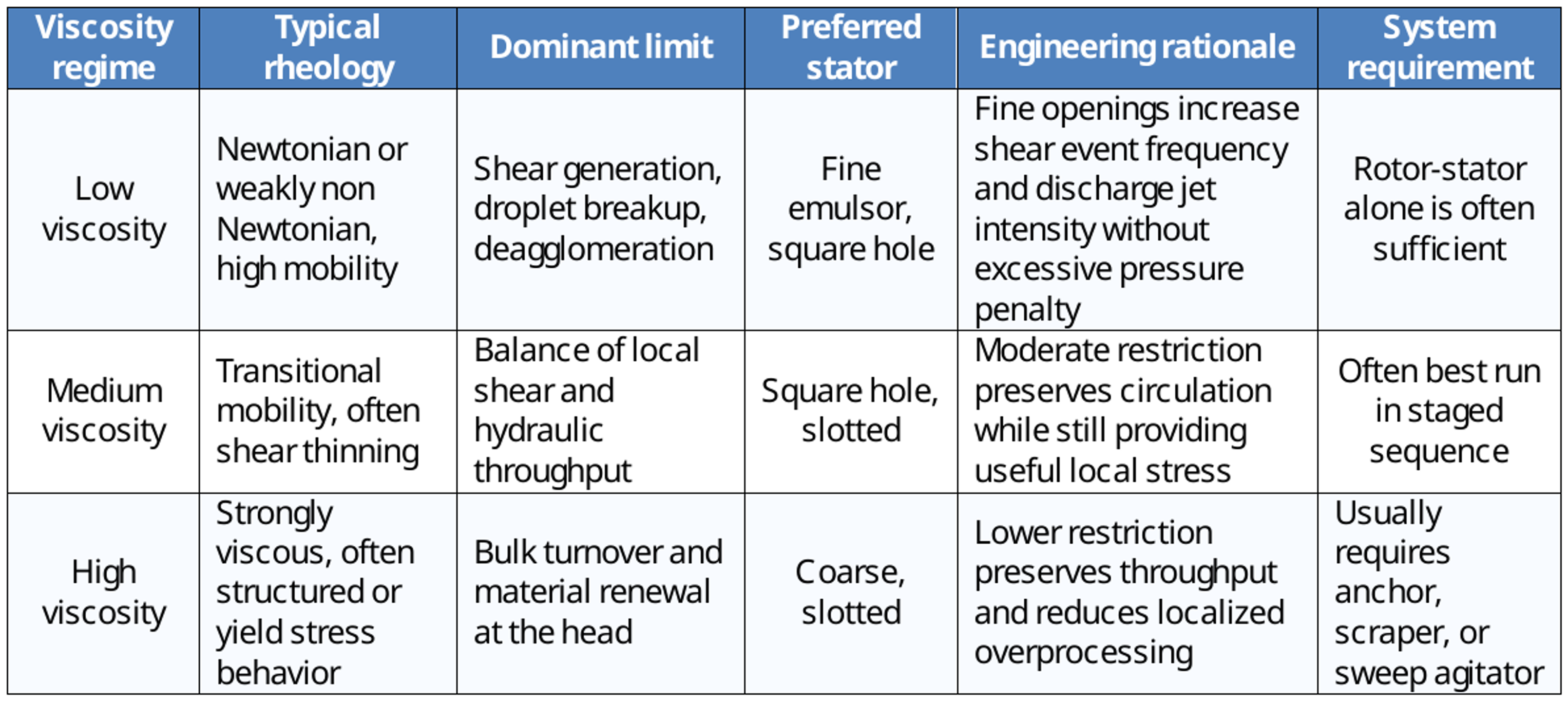
Compact stator selection table by viscosity regime
### 3.6 Design conclusion
Viscosity based stator selection is fundamentally a question of where the process bottleneck lies. In low viscosity systems, the bottleneck is usually the generation of sufficient local stress and repeated disruptive stator events. In medium viscosity systems, the bottleneck shifts toward the balance between shear intensity and hydraulic resistance. In high viscosity systems, the bottleneck is usually the renewal of material at work and the maintenance of whole vessel circulation. Accordingly, the technically correct stator choice is not simply the finest available geometry. It is the geometry that delivers the required local shear while still allowing the mixer system to process the entire batch at the required rate and uniformity.
## 4.Selection by particle type
### 4.1 Free flowing powders and soluble solids
Free flowing powders and readily soluble solids are typically handled with either coarse heads or square hole stators, depending on the controlling process limitation. If the main challenge is initial powder induction, surface wetting, or rapid turnover into the liquid phase, a coarse head is usually more effective because it generates stronger bulk recirculation and better powder drawdown. If the powder wets but forms fisheyes, hydrated shells, or persistent soft agglomerates, a square hole screen is generally the better choice because it applies to higher local shear and more effective disruptive forces after wetting has occurred. In practical terms, coarse heads are favored for ingestion and circulation, while square hole stators favor for post wetting deagglomeration and dissolution cleanup.
### 4.2 Cohesive powders, gums, hydrocolloids
Gums and hydrocolloids are typically best handled with a staged rotor-stator mixing strategy rather than immediate exposure to a fine screen. During early wetting, these materials can hydrate rapidly at the particle surface and form a viscous gel layer around an unwetted dry core. Once that outer shell develops, further liquid penetration becomes diffusion limited, and the resulting fisheyes can be difficult to eliminate. For that reason, a coarser or slotted stator is often preferred during the initial induction and wet out phase, where the priority is powder incorporation, circulation, and prevention of premature surface gelation. After the bulk of the material is uniformly wetted and the risk of shell formation has been reduced, the process can shift to a tighter screen to increase local shear and complete deagglomeration. This staged approach is especially relevant for cohesive hydrocolloids such as alginates, CMC, Carbopol, and similar gums, where the balance between wetting kinetics and shear exposure largely determines dispersion quality.
### 4.3 Fibrous, tissue like, or stringy solids
This duty generally favors slotted stators. The elongated slot geometry is less prone to fiber hang up, mat formation, and inlet blinding than a fine perforated screen. Slots provide a more continuous flow path for anisotropic, deformable, or high aspect ratio solids, allowing strands, shreds, and tissue like fragments to enter the shear zone without prematurely bridging across the stator opening. In contrast, small round perforations tend to plug when processing solids that align, wrap, or mechanically interlock at the entrance. For feeds containing fibrous or stringy material, slotted stators usually deliver better solids throughput, more stable hydraulic behavior, and lower risk of screen blockage.
### 4.4 Hard or abrasive solids
Rotor-stator heads are not always the preferred terminal device for the comminution of hard solids. Their primary strength is dispersion, wet out, and deagglomeration rather than true particle fracture of high hardness materials. Where the process objective is micronization of mineral, ceramic, or crystalline solids, the required stress intensity often exceeds what is economically or mechanically practical in a rotor-stator stage. In these cases, the rotor-stator is better treated as a preconditioning step to break soft agglomerates, homogenize the slurry, and improve feed uniformity ahead of downstream size reduction equipment. If sustained fracture of hard particles is required, the process typically shifts toward bead mills, media mills, or high pressure homogenizers, which can generate the higher localized stresses needed for effective size reduction. Abrasive solids also raise wear rates on rotor and stator surfaces, which can shorten service life, open running clearances, and reduce process consistency over time.
### 4.5 Elastic or rubbery fragments
Elastic, smear prone, or rubber like fragments generally favor slotted stator heads over fine perforated or square hole screens. These materials tend to deform, elongate, and recover under stress rather than fracture cleanly, which increases the likelihood of aperture blinding at small discrete openings. A slotted geometry provides a larger effective passage length and a less restrictive entry condition, reducing the tendency for fragments to lodge, smear across the opening, or seal the screen surface under differential pressure. In practice, this usually gives more stable flow, lower blockage risk, and better tolerance to deformable solids. Fine screens are more vulnerable when the material stretches or cold flows instead of breaking, because the feed can partially occlude the openings and progressively choke throughput. This selection logic is primarily a process engineering inference based on the known suitability of slotted heads for fibrous and elongated solids, rather than a narrowly stated equipment vendor performance claim.
## 5. Selection by emulsification duty
### 5.1 Pre-emulsion formation
For pre-emulsion duty, where the goal is to disperse one liquid phase into another before final droplet size reduction, a square hole or slotted stator is often the preferred first stage geometry. These heads generate enough shear to achieve initial dispersion while maintaining strong macrocirculation through the vessel. That balance becomes important when the oil phase is introduced rapidly or when system viscosity increases during inversion, since excessive restriction can reduce turnover and destabilize the process.
### 5.2 Final droplet refinement
For final droplet size reduction, the stator selection should move toward finer perforation patterns or multistage shear geometries. These configurations raise local shear rates, increase the frequency of droplet disruption events, and improve exposure to repeated shear, which supports smaller mean droplet size and a narrower particle size distribution.
### 5.3 Shear sensitive emulsions
Not all emulsions respond favorably to maximum shear intensity. In shear sensitive systems, excessive local energy dissipation can cause thermal rise, structural breakdown, or destabilization of the dispersed phase. In these cases, a slotted or square hole stator that provides moderate but sustained shear can outperform a fine emulsor geometry by preserving product structure while still delivering adequate dispersion and stability.
### 5.4 High internal phase or viscosity rising emulsions
For emulsions with a high internal phase ratio, or for systems in which viscosity rises rapidly during processing, stator selection must preserve macrocirculation throughout the vessel rather than maximize local shear alone. A common failure mode is selecting a fine stator too early, producing excellent shear intensity in the immediate rotor-stator zone but insufficient bulk turnover, which limits phase distribution and can stall the process. A more robust approach is to start with coarser stator geometry to establish uniform dispersion and circulation, then transition to a finer head only after the phases are well distributed. This is a practical process inference consistent with vendor guidance that emphasizes the need to balance shear generation with vessel scale circulation, particularly in high viscosity systems where sweep agitation may also be required.
## 6. Cleanability and CIP impact
Cleanability is not a secondary consideration in stator selection. In production systems, it is often one of the constraints that determines whether a head design remains practical at scale. A stator that performs well hydraulically can still fail as a production choice if it increases residue retention, extends CIP cycle time, raises disassembly frequency, or creates uncertainty in hygienic validation. For that reason, cleanability should be treated as an engineering selection variable alongside shear intensity, droplet size target, solids handling, viscosity range, and throughput.
### 6.1 Coarse and slotted heads
Coarse and slotted stators are generally the most forgiving from a CIP and washout standpoint. Their larger flow passages reduce the probability of product hold up and lower the risk of bridging by swollen powders, fibrous materials, seeds, pulp, semi gelled residues, or partially dissolved solids. From a fluid mechanical standpoint, the larger openings allow better flush velocity through the head at a given cleaning flow rate and make it less likely that residual material will remain sheltered in low exchange regions. These geometries are usually the preferred choice where the process includes difficult natural raw materials, incomplete pre hydration, botanical solids, or formulations known to leave stringy or deformable residue. They are also more robust where CIP capability is limited, where rapid turnaround is required, or where operators cannot rely on immediate post batch flushing every time. The tradeoff is obvious: the same open geometry that improves cleanability usually provides lower peak shear and less aggressive droplet or particle refinement than finer stator designs.
### 6.2 Square hole screens
Square hole screens sit in the middle of the cleanability range. They can usually be cleaned successfully in sanitary systems, but they are less tolerant than coarse or slotted heads when the batch contains sticky agglomerates, partially hydrated powders, proteinaceous deposits, or materials that dry into tenacious films. The smaller and more numerous apertures increase internal wetted perimeter and create more opportunities for local retention. In practice, cleaning performance depends strongly on operating discipline. Immediate post run flushing, adequate solution temperature, sufficient CIP flow velocity, and avoidance of extended hold time before cleaning all matter more with this geometry. If product is allowed to dry, gel, or crystallize inside the perforations, cleaning time and verification burden rise quickly. Square hole screens are therefore often a reasonable compromise where moderate particle size reduction or dispersion quality is needed, but the formulation is still manageable from a sanitation standpoint.
### 6.3 Fine emulsor screens
Fine emulsor screens are usually the most demanding option for CIP and hygienic maintenance. Their small perforations and high edge density are valuable for generating high local shear, but those same geometric features increase the likelihood of residue retention and make the head less tolerant of materials that smear, gel, crystallize, or partially solidify. This is especially relevant for proteins, hydrocolloids, wax bearing systems, fat containing products, sticky concentrates, and formulations with incomplete solvation. From an engineering perspective, the issue is not just "small holes are harder to clean." The finer geometry increases internal surface area, reduces characteristic passage dimension, and makes removal of adherent residue more dependent on cleaning chemistry, temperature, and local wall shear during CIP. As a result, these heads often require tighter cleaning control, warmer flush media, higher CIP velocities, more aggressive chemical sequencing, or more frequent manual inspection and disassembly. Fine emulsor heads can still be the correct process choice when the required emulsion quality or dispersion fineness justifies the sanitation burden. But that burden should be explicitly accounted for during selection rather than discovered later in production.
### 6.4 Hygienic processing note
For hygienic service, stator selection cannot be reduced to aperture pattern alone. Cleanability must be evaluated at the assembly and system level. The relevant question is not only whether the stator itself is easy to flush, but whether the full mixing head and surrounding wetted envelope can be cleaned, drained, inspected, and returned to service in a controlled and repeatable way.
That evaluation should include at least the following factors:
- access to the head for inspection, manual verification, and washdown
- drainability of the assembly in installed orientation
- seal design and suitability for hygienic duty
- internal surface finish and weld quality
- elimination of crevices, dead legs, and shadowed flow regions
- ease of disassembly and reassembly of wetted components
- compatibility with CIP chemistry, temperature, and flow regime
- validation burden for allergen, flavor, bioburden, or product changeover control
In food, dairy, beverage, personal care, and biopharma applications, these factors can carry as much weight as hydraulic performance. A stator pattern may look optimal for emulsification or dispersion duty yet still be the wrong engineering choice if it traps product, creates persistent low exchange regions, complicated CIP validation, or increases maintenance exposure. For that reason, stator selection should be handled as a multicriteria design decision. Sanitary construction, hygienic serviceability, and maintainability should be formal selection criteria, not afterthoughts, and should be weighed directly against emulsification duty, particle reduction target, viscosity window, solids sensitivity, and required throughput.
## 7. Decision matrix
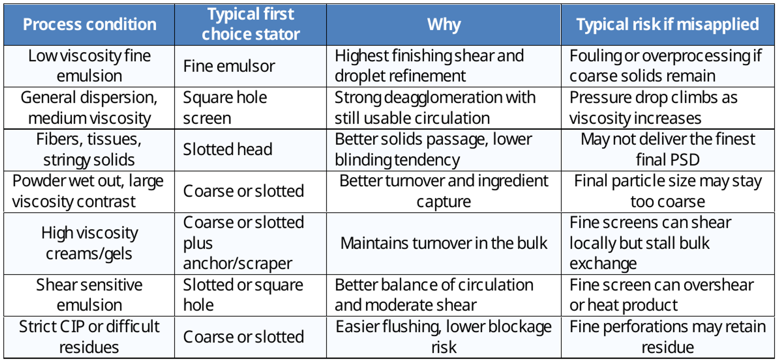
Decision matrix for stator selection by process condition
## 8. Engineering selection rules
### Rule 1
When selection uncertainty exists, prioritize macroscopic circulation and batch turnover before maximizing local shear intensity. A rotor-stator head that generates very high shear in a small hydraulic capture zone can underperform a slightly less aggressive geometry that entrains a larger fraction of the vessel contents per unit time. In practical terms, whole batch processing rate is often controlled as much by pumping capacity and recirculation pattern as by tip zone stress. For scale up and process robustness, first confirm that the selected head can sustain adequate top to bottom turnover, eliminate stagnant regions, and repeatedly return unprocessed material to the work head.
### Rule 2
Use fine screen geometry as a finishing step rather than as the primary incorporation tool. Fine emulsor or fine perforated stators impose higher hydraulic resistance, narrower flow passages, and greater sensitivity to viscosity growth, powder loading, and soft agglomerates. That makes them better suited to late stage droplet size reduction or final dispersion refinement after the formulation is already wetted, deagglomerated, and flowing consistently. In early stage mixing, a less restrictive head usually gives better solids acceptance, lower plugging risk, and more stable throughput.
### Rule 3
In high viscosity service, improve system level flow before escalating stator restriction. As viscosity rises, rotor-stator performance becomes increasingly limited by material transport into and out of the active zone. Under those conditions, selecting a finer stator alone often increases pressure drop and reduces effective circulation without proportionally improving real process intensity. The better engineering solution is frequently a rotor-stator head paired with an auxiliary flow generating device such as an anchor, scraper, sweep agitator, or dedicated recirculation loop. This keeps fresh material moving through the shear zone and prevents the process from becoming locally intense but globally inefficient.
### Rule 4
For fibrous, deformable, or gummy feedstocks, default toward slotted stators unless fouling data proves that a perforated screen will remain open. These materials tend to bridge, mat, or smear across round or square perforations, which reduces open area, increases pressure drop, and destabilizes throughput. Slot geometry generally provides a more tolerant flow path, better resistance to blinding, and more reliable passage of elongated or elastic structures. The decision should be based on expected particle morphology under shear, not only on nominal starting particle size.
## 9. Bottom line engineering selection guidance
Use coarse disintegrating heads when the controlling requirement is hydraulic throughput, whole vessel turnover, solids ingestion, and tolerance to broad viscosity variation. These heads are usually the safest first choice for initial incorporation, bulk recirculation, and difficult feeds that would overload finer stators.
Use square hole screens when the duty requires the best general purpose balance between shear generation, throughput, and operating practicality. They are often the most versatile option for routine dispersions and many emulsification services where neither extreme fineness nor extreme fouling resistance is the primary design driver.
Use slotted heads when the formulation contains fibrous, stringy, elastic, or tacky material, or when viscosity is high enough that screen restriction becomes a process bottleneck. Their advantage is not simply lower plugging risk, but better preservation of usable flow under difficult rheology and nonideal particle morphology.
Use fine screen heads only after the process is already conditioned for them. Their proper role is final stage droplet refinement, tight particle size reduction, or finishing of an already well wet and mobile system. They are usually poor choices for first contact powder incorporation or for feeds likely to blind the stator.
Use multistage and toothed work heads when the process economics favor tighter structural control, fewer recirculation passes, and improved reproducibility over maximum simplicity or raw throughput. These geometries are most justified when the target product requires a narrower final distribution, more repeatable endpoint, or higher energy density within a controlled residence path.
## Note on terminology and evidence basis
*Specific work head names such as Coarse Disintegrating Head, Square Hole Screen, Standard Emulsor Screen, Fine Emulsor Screen, and Slotted Head follow commercial rotor-stator mixer nomenclature used by equipment suppliers. General engineering claims in this article are based on peer reviewed rotor-stator literature concerning shear generation, emulsification, hydraulic behavior, and scale up. Where a statement maps general process physics to a named commercial head type, that statement should be read as process engineering interpretation unless a comparative experimental source is cited directly for that geometry.*
## References
1. Hakansson, A. (2018). Rotor-stator mixers: From batch to continuous mode of operation. A review. Processes, 6(4), 32.
2. Hall, S., Pacek, A. W., Kowalski, A. J., & Rothman, D. (2013). The effect of scale and interfacial tension on liquid-liquid dispersion in inline rotor-stator mixers. Chemical Engineering Research and Design, 91, 2156-2168.
3. Qin, L., Xu, B., Zhang, Y., & others. (2017). Effect of stator geometry on the emulsification and extraction in the inline single row blade screen high shear mixer. Industrial & Engineering Chemistry Research.
4. Silverson. (2022). Laboratory scale mixers [Product brochure].
5. IKA. Dispersers and homogenizers overview.